Ups general description & installation
OM226130 Rev. A 7
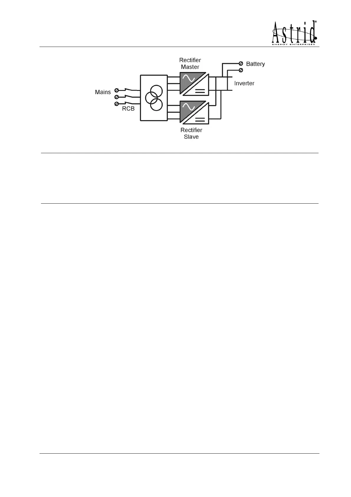
Picture 3 - 12 pulses rectifier with galvanic isolation
WARNING
The mechanical dimensions of UPS’s with the 12 pulses rectifier are different from
those indicated at paragraph 3.3.1 and 3.3.2. These configurations are always tied to
specific requirements of the purchaser, so the mechanical configuration is defined time
by time.
Contact the technical office for further information.
2.2.3 Inverter
It converts the continuous voltage coming from the rectifier or from the battery into
alternating voltage stabilized in amplitude and frequency.
The inverter uses IGBT technology with a frequency commutation of approximately
10 KHz.
The control electronics is completely digital and uses a 16 Bit µP, that, thanks to its
processing capability, generates an excellent output sine-wave, which has a very low
distortion even in presence of loads having high crest factor currents.
2.2.4 Battery and battery charger
On the PLANET E 20-30kVA and HALLEY E 20-30kVA UPS battery can be located
inside the UPS for autonomy from 5 up to 15 minutes depending on the UPS power
(see tables page 12); on the other hand, battery is placed on external cabinet.
Warning: only the PLANET E 20-30kVA and HALLEY E 20-30kVA UPS can have
internal batteries. The UPS with bigger sizes have to be placed on external battery
cabinets.
The battery charger control logic is completely integrated inside the total-controlled
rectifier control board; the battery is charged, according to the DIN 41773 Standard,
every time it has been partially or completely discharged and it is kept floating, even
when it’s charged, to compensate for any autodischarge.
2.2.5 Static bypass
It’s designed to transfer the load between INVERTER and MAINS, and vice-versa,
without break, and uses SCR’s as power commutation elements.