29
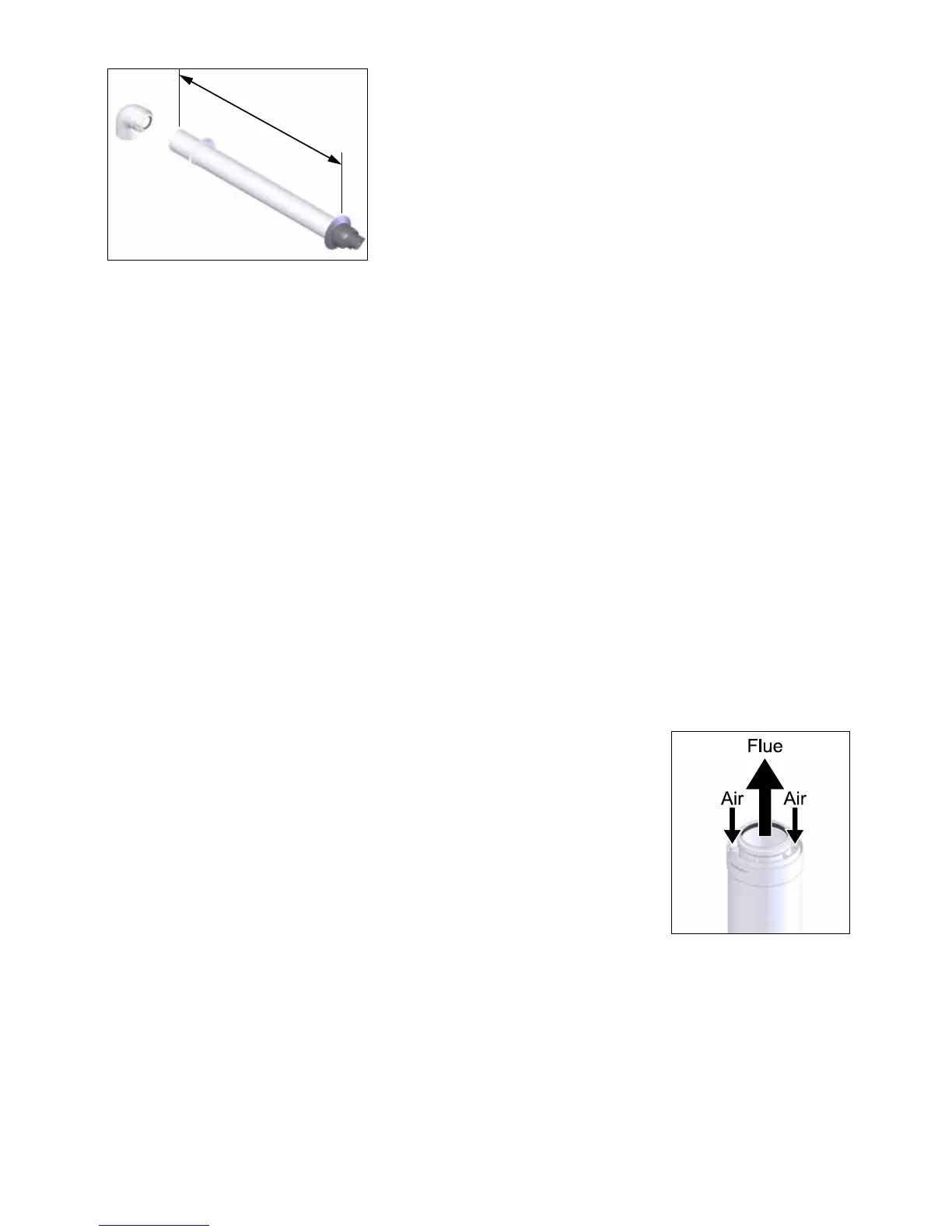
Flow direction Figure 9.8.2.b
Rear Flue
L = wall thickness (B) + 150mm
Side Flue
L = wall thickness (B) + distance between boiler and wall (C) + 150mm
If the length L is more than 580mm rear ue or 585mm side ue, then a
Horizontal ue xed length 1000mm (60/100mm) with elbow (FA100205)
will need to be used instead, up to 810mm.
Note: If it is required to cut an extension, DO NOT cut the end of the inner duct that incorporates the seal
joint.
Ensure the inner duct end without the seal joint is cut so that it is ush with the outer duct.
Ensure that all cuts are square and free from burrs.
Once assembled with the components pushed home, the ue is fully sealed.
1. Adjust the telescopic ue and secure with sealing tape supplied or cut the xed length terminal ue to the
required length.
2. Fit the ue to the extensions (if required) by locating the inner duct into the seal joint and push fully home
the inner and outer duct.
3. When connecting the horizontal ue terminal length ensure the terminal end outlet is at the uppermost
part of the ue.
4. Pass the terminal ue assembly through the wall.
5. Fit the bend to the boiler turret.
6. If the inside sealing collar (white) is being used, then it will need to be tted before assembling the ue
and making good the inside wall.
7. Pull the ue assembly towards the bend, locating the inner duct into the seal joint on the bend and secure
the ue assembly to the bend by pushing fully home (Outer ue duct must be seen through the small
inspection hole to conrm fully home).
8. Make good the outside wall and t the outside sealing collar onto the location provided immediately
behind the ue terminal grille.
When mounting the ue gas system, pay attention to the ow direction (See
gure 9.8.2.b). It is not permitted to mount a system upside down and will lead to
complaints.
Use the special grease (supplied in the accessory bag with the boiler) to simplify
the tting.
The ATAG ue system used is a push t ue system, which does not require
screws to be tted at each ue joint.
The ue system must be adequately supported at regular intervals between
brackets of no more than 1.0 metres for horizontal sections and no more than
2.0 metres for vertical sections.
L
Figure 9.8.2.a

 Loading...


