25
9.8.1 Flue terminal locations
The terminal should be located where dispersal of combustion products is not unimpeded and with due
regard for the damage or discolouration that might occur to parts of the building in the vicinity (see g
9.8.1.c).
In certain weather conditions condensation may also accumulate on the outside of the air inlet pipe. Such
conditions must be considered and where necessary insulation of the inlet pipe may be required.
In cold and/or humid weather water vapour may condense on leaving the ue terminal. The eect of such
‘plumeing’ must be considered.
The terminal must not be located in a place where it is likely to cause a nuisance, where the terminal is less
than 2m (6.6ft) above a pavement or platform to which people have access (including) any balcony or at
roof. The terminal must be protected by a guard of durable material.
horizontal, and the window opens outwards, the terminal shall be 1m below the bottom of the window
opening.
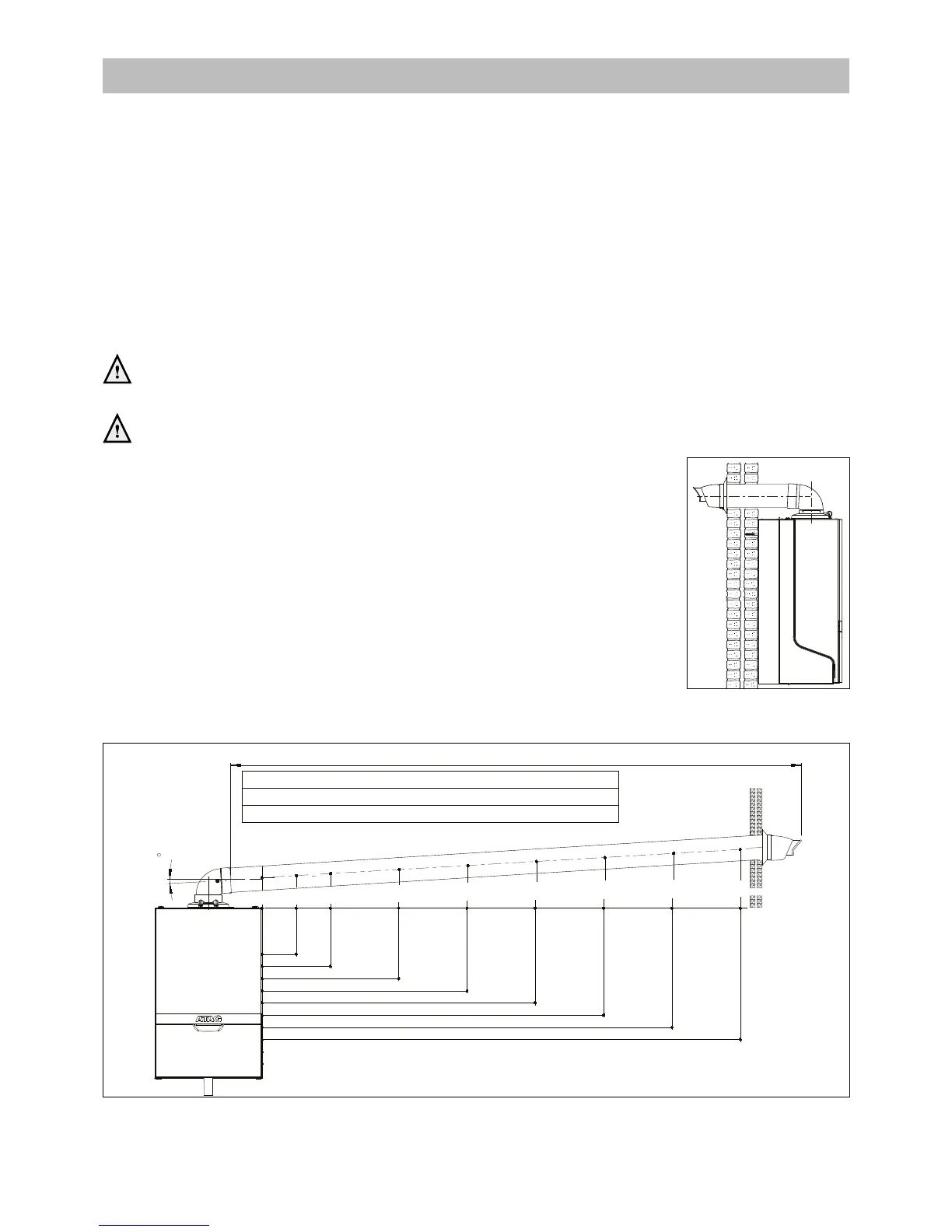
For horizontal ue terminal direct to the rear or side through the wall (only 1 bend
and 1 wall terminal) the terminal should be placed horizontal. The ue pipe inside
the terminal is tted in a 3 degrees angle to ensure the condensation water can run
back to the boiler. See gure 9.8.1.a.
For longer horizontal sections, the outlet system should always be tted on an
incline (52 mm/m = 3°) sloping down towards the boiler so that no condensation
water is able to accumulate in the outlet system. The chances of icicles forming on
the outlet is minimised by causing the condensation water to run back towards the
boiler. See gure 9.8.1.b.
Figure 9.8.1.a
Figure 9.8.1.b
15 m : i24C/i28C iC Economiser 27 Plus i15R/i18R/i24R i15S/i18S/i24S
9 m : i36C/i40C i32R/i40R i32S/i40S
Elbow or
vertical adapter
225mm
121mm
8 m : iC Economiser 35 Plus / iC Economiser 39 Plus
330mm
435mm
540mm
645mm
749mm
854mm
2 m
4 m
6 m
8 m
10 m
12 m
14 m
3
Maximum straight length for Ø60/100:
173mm
1 m

 Loading...


