53
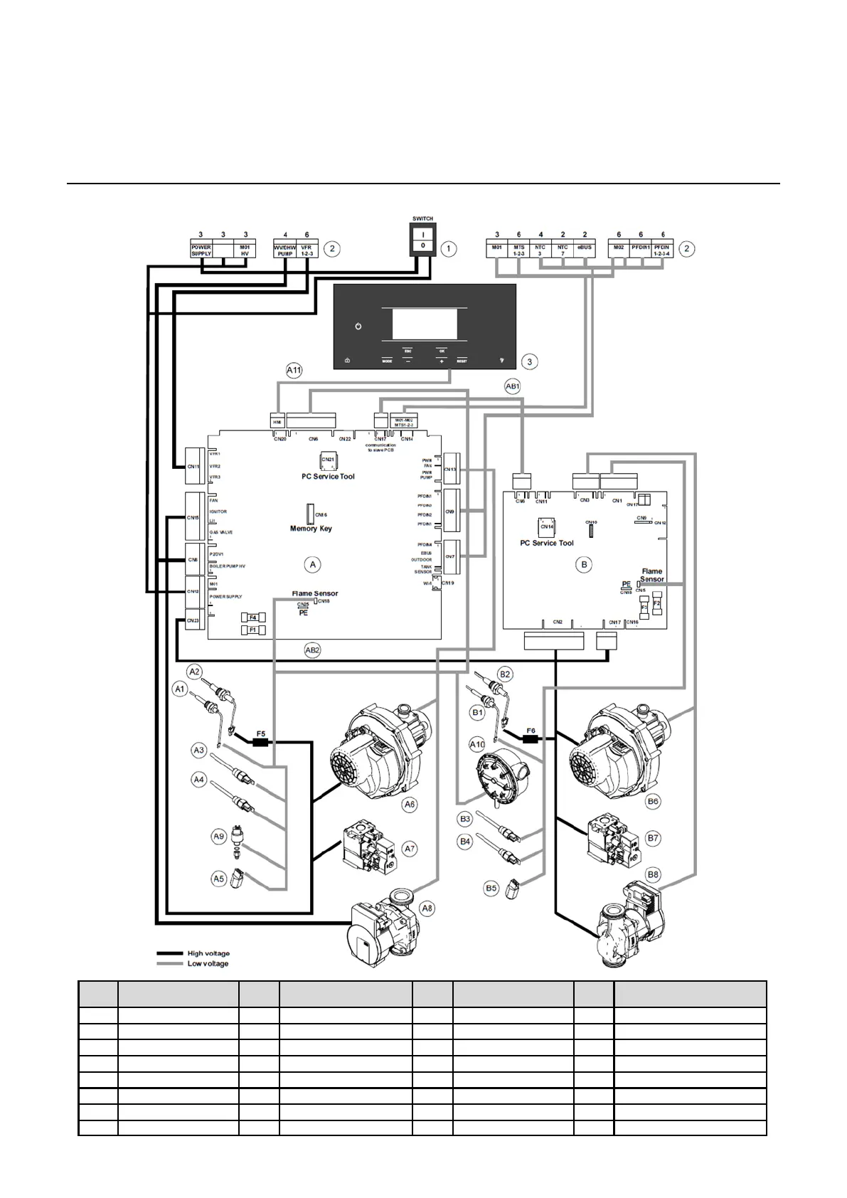
Boiler Installation
Electrical connection
Pos
.
Description
Pos
.
Description
Pos
.
Description
Pos
.
Description
1 Main switch 230V A5 Return temp sensor B1 Ionisation electrode AB1 Fuse 6.3A - 250V
2 Electrical connect. A6 Fan unit B2 Glow igniter AB2 Fuse 6.3A - 250V
3 HMI A7 Gas valve B3 Flow temp sensor F1 Fuse 6.3A - 250V
A Master PCB A8 Circulation pump B4 2
nd
flow temp sensor F2 Fuse 6.3A - 250V
A1 Ionisation electrode A9 Water pressure sensor B5 Return temp sensor F3 Fuse 3.15A - 250V
A2 Glow igniter A10 Air pressure switch B6 Fan unit F4 Fuse 3.15A - 250V
A3 Flow temp sensor A11 HMI comm cable LV B7 Gas valve F5 Fuse 6.3A-250V-4.2I
2
t-fast
A4 2
nd
flow temp sensor B Slave PCB B8 Circulation pump F6
Fuse 6.3A-250V-4.2I
2
t-fast
Wiring Diagram
 Loading...


