Installation
Parts list
• Telephonelinecord
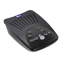
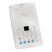
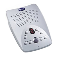
• 1739answeringsystem
• Walletcard
• Part1Importantproductinformation
• Part2User’smanual
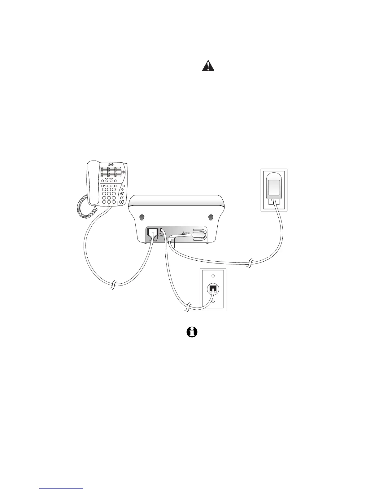
Before you install
Choosealocationfortheansweringsystem
nearamodulartelephonejackandastandard
electricaloutletnotcontrolledbyawall
switch.
Turn system on/off
Beforeproceedingtofeaturesetup,press
ON/OFFtoturnthesystemon.Toturnthe
systemoff,pressON/OFFagain.
Whenthesystemisoff,theON/OFF
indicatorlightwillbeoffandthemessage
windowwillbeblank.
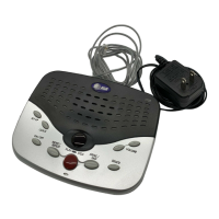
Use only the power adapter
supplied with this product. To
obtain a replacement, visit our
website at www.telephones.att.com
or call 1 (800) 222-3111. In Canada
dial 1 (866) 288-4268.
NOTES: 1. If you do not want to connect this
answering system to a telephone,
skip to step 3.
2. Power adapter Input: 120VAC, 60
Hz, 4.5W. Output: 6VAC, 350 mA.
3. If the message window is blank,
make sure the power adapter is
securely connected to both the
answering system and an electrical
outlet not controlled by a wall
switch. Press ON/OFF to make
sure the system is on.