bc cb
USE ONLY WITH
COMMUNICATION
CIRCUIT POWER
SOURCE
ADB|TMI
FEATURE PACKAGE X.X
Place
Label
Here
c
c
c
c
c
c
c
c
c
c
c
c
c
bbbbbbbbbbbbbbbbbbbbbbbbbbbbbbbbbbbbbbbbbbb
c
c
c
c
c
c
c
c
c
c
c
c
cbbbbbbbbbbbbbbbbbbbbbbbbbbbbbbbbbbbbbbbbbbb
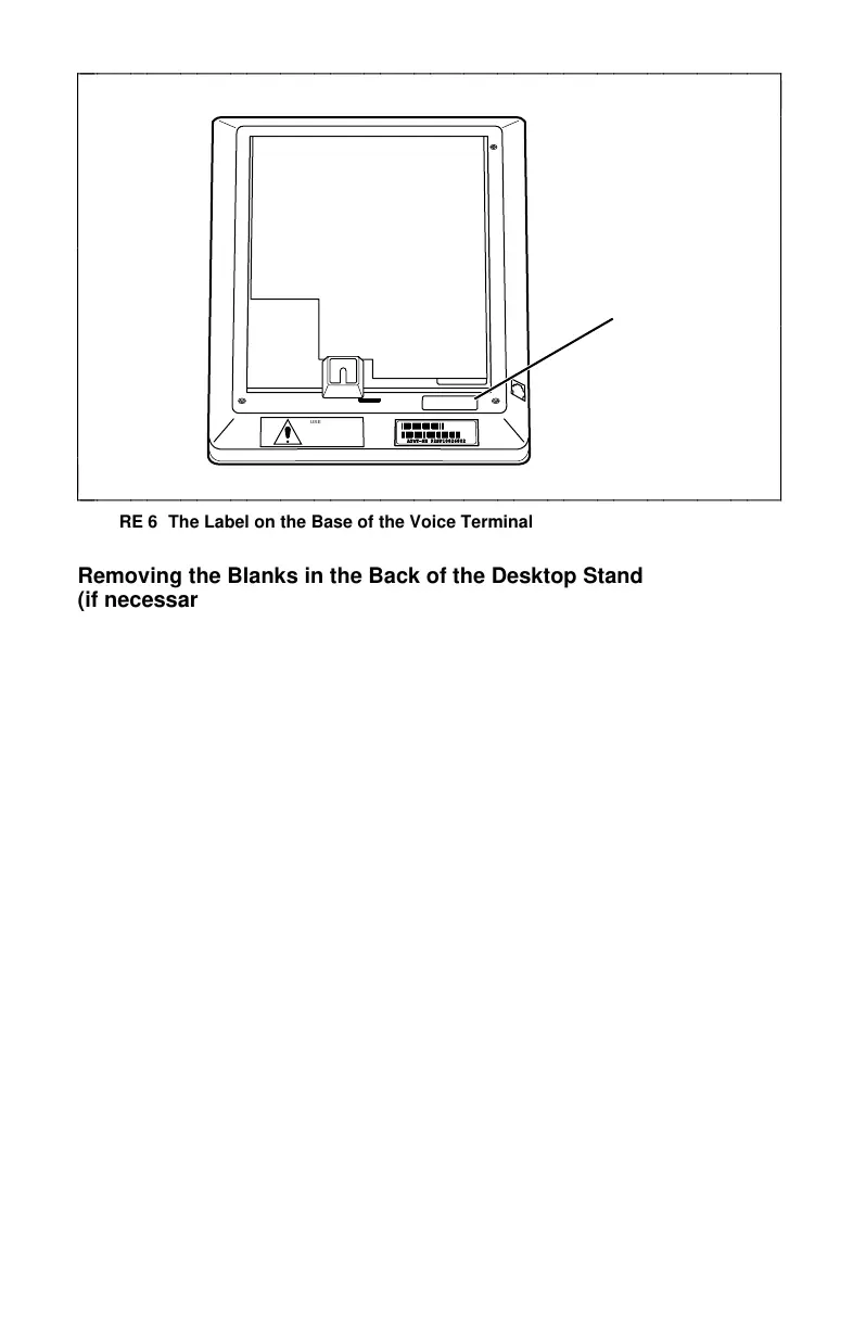
FIGURE 6 The Label on the Base of the Voice Terminal
Removing the Blanks in the Back of the Desktop Stand
(if necessary)
Before you can reinstall the desktop stand on the base of the terminal,
the blanks which cover the connector holes on the rear of the stand must
be removed. If you have already completed this procedure when
installing the ADB or TMI board, go on to ‘‘Reinstalling the Desktop
Stand.’’
If you have not removed the connector hole blanks, follow this
procedure.
1 Turn the desktop stand so that you can see the blanks which cover
the holes for the RS232 connector (the long rectangular blank) and
the 8-pin round connector (the square blank). For the location of
these blanks, see Figure 7.
10
fc cf
 Loading...
