bc cb
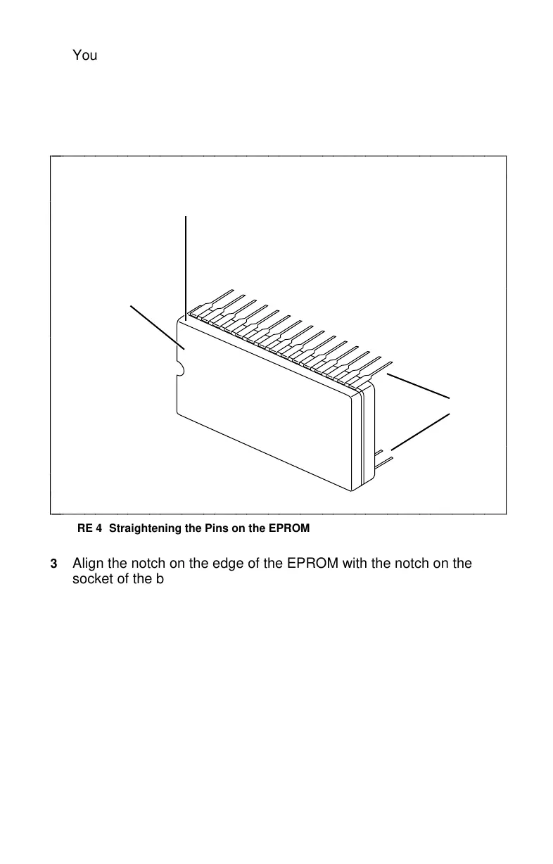
You can do this by placing the pins on a flat, non-metallic surface and
pushing on the chip body until the pins are straight. See Figure 4.
Repeat this process on the other side of the EPROM.
NOTE: You may need to rock the EPROM back and forth against the
desk in order to bend the pins so that they fit the socket.
EPROM
Pins
Push here on
chip body
c
c
c
c
c
c
c
c
c
c
c
c
c
c
c
c
bbbbbbbbbbbbbbbbbbbbbbbbbbbbbbbbbbbbbbbbbbb
c
c
c
c
c
c
c
c
c
c
c
c
c
c
c
cbbbbbbbbbbbbbbbbbbbbbbbbbbbbbbbbbbbbbbbbbbb
FIGURE 4 Straightening the Pins on the EPROM
3 Align the notch on the edge of the EPROM with the notch on the
socket of the board. Make certain these notches are facing the same
direction. You may need to repeat Step 2 until the pins line up with
the socket receptacles.
4 To install the new EPROM, carefully align the pins of the EPROM
with the corresponding receptacles in the EPROM socket. See
Figure 5.
NOTE: Figure 5 shows a TMI board; however, the location of the
EPROM is the same on both the ADB and the TMI boards.
5 Insert the EPROM into the socket and press the EPROM firmly into
place.
8
fc cf
 Loading...
