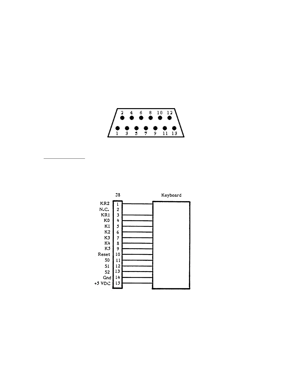
Figure 1-9 is an illustration of the SIO pin assignments.
PIN PIN
1 Clock In 7 Command
2 Clock Out 8 Motor Control
3 Data Into CPU 9 Proceed
4 GND 10 Ready (Computer ON)
5 Data Out 11 Audio In (175 MV)
6 GND 12 +12 VDC (Not used on 1200XL)
13 Interrupt
Figure 1-9. SIO Interface Pin Assignments (looking into jack on unit)
Keyboard Interface
Figure 1-10 is an illustration of the keyboard interface pin assignments.
The 1200XL keyboard uses a 15-pin Molex Connector, which provides inputs to POKEY,
GTIA (SO,S1,S2) and CPU (Reset).
Figure 1-10. Keyboard Interface Pin Assignments.
1200XL Home Computer
Field Service Manual 1-13
 Loading...


