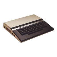
KEYBOARD REMOVAL/REPLACEMENT
1. Remove the top cover from the console.
2. Remove the keyboard connector and LED connector. Note the position of the LED
connector for reference during assembly.
3. Remove the four screws which hold the keyboard to the top cover. 4. Remove the
keyboard from the top cover.
TO REPLACE THE KEYBOARD
1. Place the top cover upside down on the workbench. 2. Install and position the new
keyboard.
2. Insert and tighten the four screws which hold the keyboard to the top cover.
3. Attach the keyboard connector and the LED connector (Be careful not to twist the
LED connector cable).
RF MODULATOR ADJUSTMENT
1. Disassemble the console (See Page 4-3).
2. Remove the RF Shield.
3. Adjust RF modulator for correct Color Bar Test Screen (See Page 3-5, Figure 3-3).
4. Replace the RF Shield.
NOTE: RF modulator may also be adjusted using a frequency meter.
Procedure:
• Connect the frequency meter to the RF output jack on the modulator (A3).
• Set SW3 to Channel 3 position. Adjust modulator to 61.25 MHz.
SOUND ADJUSTMENT
See Figure 4-1, Page 4-2.
Adjustment can be made through top or bottom cover.
COLOR ADJUSTMENT
See Figure 4-1, Page 4-2.
Adjustment can be made through top or bottom cover.
1200XL Home Computer
Field Service Manual 4-4

 Loading...