-
Graphic Television Interface Adaptor (GTIX)
-
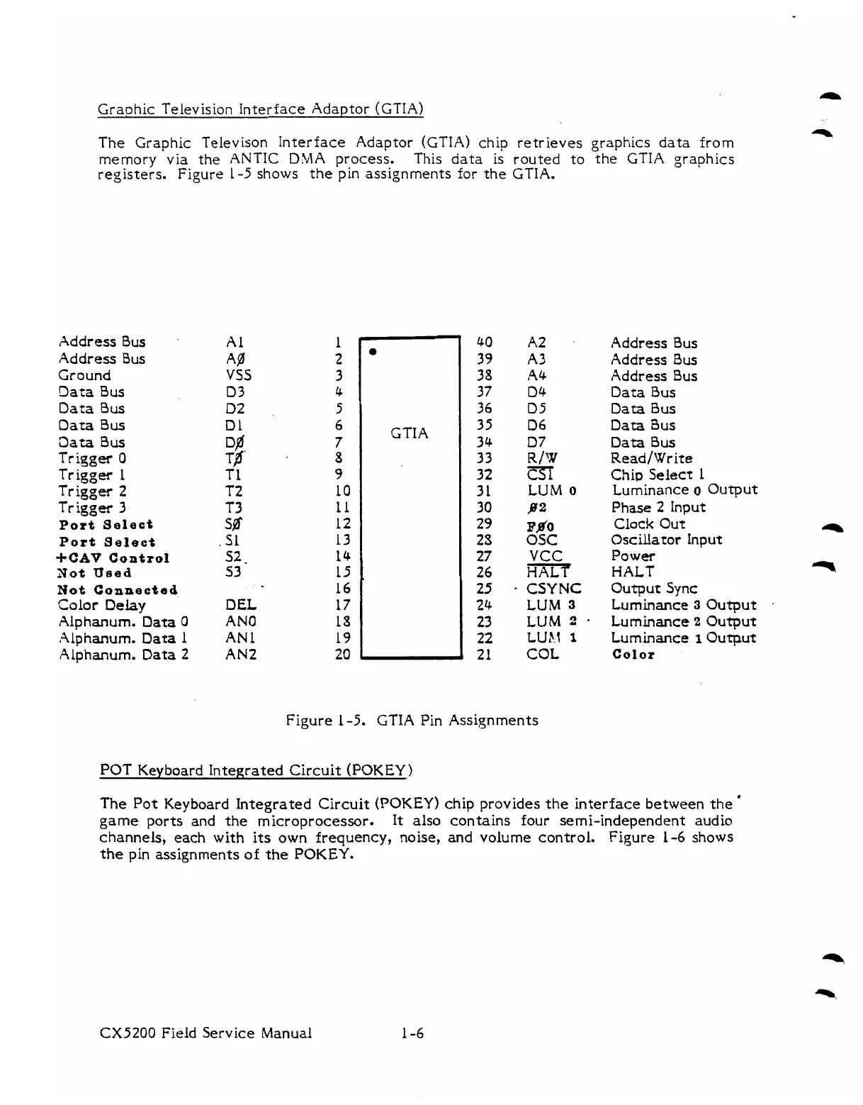
The Graphic Televison Interface Adaptor
(GTIA)
chip retrieves graphics data from
memory
via the ANTIC
DMA
process.
This data is routed to the GTIA graphics
registers. Figure 1-5 shows the pin assignments for the GTIA.
Address
Bus
Address
Bus
Ground
Data
Bus
Dara
Bus
Oata
Bus
aata
Bus
Trigger
0
Trigger
1
Trigger
2
Trigger
3
Port
Select
Port
Select
+CAP
Control
Not
Used
Not
Connectad
Color
Delay
Alphanum-
Data
0
Alphanum.
Data
1
Alphanum-
Data
2
A1
A%
VSS
03
D2
Dl
Yf.
T1
T2
T3
sff
.
S1
s2.
53
..
DEL
AN0
AN
1
AN2
0
GTIA
A2
A3
A4
Dk
D5
06
D7
R/Y
m
LUM
o
a2
Fa'0
OSC
VCC
HALr
CSY
NC
LUM
3
LUM
2
-
LUt.1
1
COL
Address
Bus
Address
Bus
Address
Bus
Oata
Bus
Data
Bus
Data
3us
Data
Bus
Read/Write
Chip
Select 1
Luminance
o
Output
Phase
2
Input
Clock
Out
e
Oscillator
Input
Power
HALT
q
Output
Sync
Luminance
3
Output
.
Luminance
2
Output
Luminance
I
Output
Color
Figure 1-5. GTIA Pin Assignments
POT
Keyboard Integrated Circuit
(POKEY)
The Pot Keyboard Integrated Circuit
(POKEY)
chip provides the interface between the
'
game
ports and the microprocessor. It also contains four semi-independent audio
channels, each with its own frequency, noise, and volume control. Figure
1-6
shows
the pin assignments of
the
POKEY.
CX5200
Field Service Manual