Ground
Data
Bus
Data
Bus
Data
Bus
Data
Bus
Data
Bus
Phase
2
Clock
Pot
Scan
Pot
Scan
Pot
Scan
Pot
Scan
Pot
Scan
Pot
Scan
Pot
Scan
Pot
Scan
Softfire
5
V
Power
Not
Connected
:<ey
board
Scan
Keyboard
Scan
e
VSS
03
D4
D5
D6
07
#2
P6
P7
P4
P5
PZ
P3
PO
VCC
-
K5
i(4
K3
0
POKEY
D2
Dl
DO
AUDIO
A0
A1
A2
A3
R/W
CS
1
cso
-
IRQ
SOD
OCLK
BCLK
-
KRl
SID
K(;
K1
-
K2
Data
Bus
Data
Bus
Data
Bus
Audio
Out
Address
Bus
Address
Bus
Address
Bus
Address
Bus
Read/Write
Control
Chip
Select
Chip
Select
Interrupt
Request
Serial
Output
Data
Serial
Output
Clock
Bidirectional
Clock
Xeyboard
Read
Serial
lnput
Data
Net
Cennec*ed
Keyboard
Scan
Keyboard
Scan
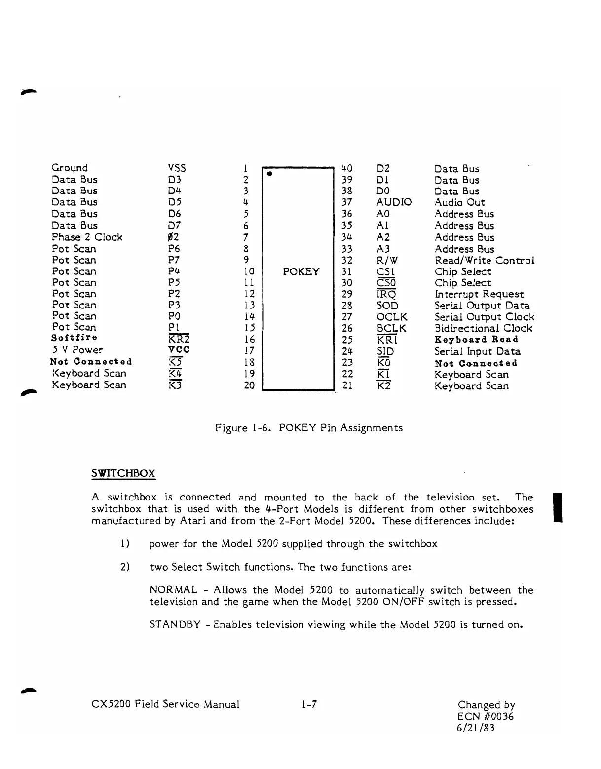
Figure
1-6.
POKEY
Pin Assignments
A switchbox is connected and mounted to the back of the television set.
The
switchbox that is used
with
the 4-Port Models
is
different from other switchboxes
manufactured
by
Atari and from the 2-Port Model 5200.
These differences include:
1
2)
two Select Switch functions. The two functions are:
NORMAL
-
Allows the Model
5200
to automatically switch between the
television and the
game
when the Model 5200
ON/OFF
switch is pressed.
STANDBY
-
Enables television
viewing
while
the Model
5200
is turned
on.
CX5200
Field Service Manual Changed
by
ECN
/I0036
6/21
/83