Consumer
Product
Service
Manager
of
Tehnicai
Support
vcs
TECH
Tlf
number
.-
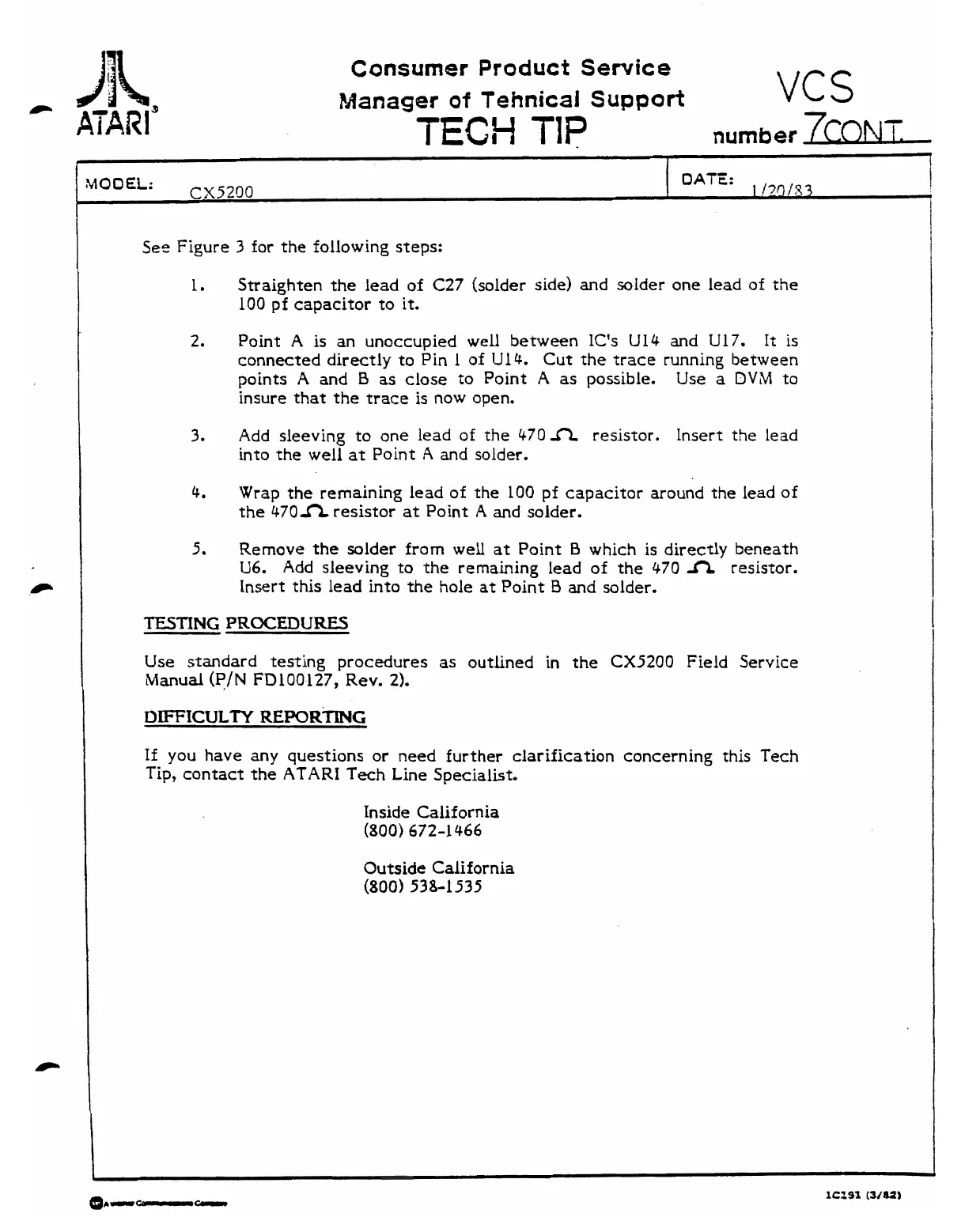
See Figure
3
for the following steps:
-
1.
Straighten the lead of
C27
(solder side) and solder one
lead
of the
100
pf
capacitor to it.
--
DATE:
1
/7g/x3
2.
Point A is an unoccupied
well
between IC's
Ul4
and
U17.
It
is
connected directly to Pin 1 of Ul4. Cut the trace running between
points
A
and
B
as close to Point
A
as
possible. Use
a
DVM
to
insure that the trace is now open.
3.
Add sleeving to one lead of the
470
n
resistor. Insert the
lead
into the well
at
Point
A
and solder.
4.
Wrap the remaining lead of the
100
pf capacitor around the lead
of
the
470n
resistor
at
Point
A
and solder.
5.
Remove the solder from well at Point
B
which is directly beneath
U6.
Add sleeving
to
the remaining lead of the
470
A.
resistor.
Insert this lead into the hole at Point
B
and solder.
TESTING
PROCEDURES
Use
standard
testing procedures
as
outlined in the
CX5200
Field Service
Manual
(PIN
FD100-127,
Rev.
2).
DIFFICULTY
REPORTING
If
you have any questions or need further clarification concerning this Tech
Tip, contact the
ATARI
Tech
Line Specialist.
Inside California
(800)
672-1466
Outside California
(800) 538-1 535