SECTION
1
THEORY
OF
OPERATION
Over view
The ATARI Advanced Video Entertainment System (Model 5200) is an advanced
microcomputer. It receives input from the game controllers, Read-Only-Memory
(ROM) cartridges and other peripherals, and displays this input on
a
T.V. screen.
A
maximum of four players may play at one time.
The
Model
5200
is composed of the console, switchbox and game controllers.
The
following paragraphs provide
a
general discussion of each of these items and their
component parts. For
a
detailed discussion of the Game Controller see SECTION
6.
Model
5200
CONSOLE
The Model 5200 console is composed of
an
outer plastic
case
which houses the
PC
board and its
RF
Shield.
Figure 1-1 shows the console and its parts.
There
are
currently
three
different
PC
Boards
being
used
in
Model
5200
consoles.
Some
models
contain
the
original
4-port
PC
Board, number CA018087.
Other
consoles
contain
a
4-port
universal
PC
krd,
number
CA020108. A third
PC
Board
with
only
two
player
ports,
number
CA021374,
is
also
available.
Unless
otherwise
specified,
the
references
in
this
manual
pertain
to
the
original 4-port
PCB,
number
CA018087.
The
specific
differences
of
the
4-port
universal PCB
and
the
2-port universal PCB
are
called
out
below.
Four-Port
Universal PCB
differences
External
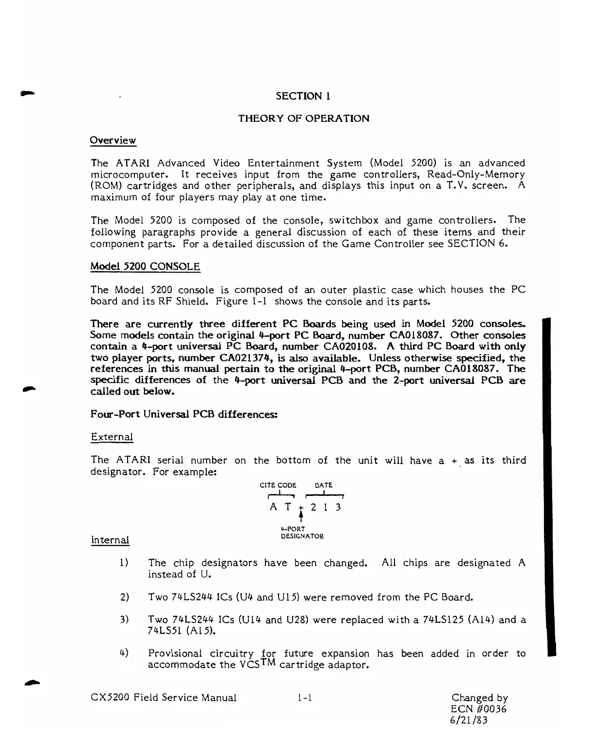
The ATARI serial number on the bottom of the unit will have
a
+
as
its third
designator.
For
example:
CITE
CODE
DATE
Q-PORT
DESIGN
ATOF
The chip designators have been changed. All chips are designated
A
instead of
U.
Two 74LS244 ICs
(U4
and U15) were removed from the
PC
Board.
Two 74LS244 ICs (Ul4 and U28) were replaced with a 74LS125 (Al4) and
a
74LS51 (A15).
Provisional circuitry for future expansion has been added in order to
accommodate the
vcsTM
cartridge adaptor.
CX5200 Field Service Manual
1-1
Changed by
ECN
/I0036
6/21
/83