Video Troubleshooting Table
SYMPTOM CAUSE REQUIRED ACTION
1
.
Monitor appears non-
functional
.
Audio is present
.
VGM controls operate
normally
A
1
l
Power problem
Faulty wiring
Improper monitor
adjustments
Verify connection of AC Power to video monitor.
Inspect CRT neck in dim light. Glowing filament
near CRT base proves that some monitor
circuits receive power. Still, voltages or signals
may not be normal.
1.
Turn off VGM power. Verify that video signal and
Remote Adjustment Board connectors seat
properly on Video Monitor Board.
2. Assure that video cables connect to circuit
boards.
3.
Assure
that
no wires
aie
Caii$ii
Ofi
&iZSSiS Oi
mounting brackets.
Check that BRIGHTNESS (intensity) and
I
CONTRAST are set above their minimum tevels.
1 1. Examine AC line fuse on Video Monitor Board. If
fuse is faulty, replace it with identical fuse.
2. If fuse is good: Verify that video monitor
4. If
power’s;ply
is good: Check
mo;or
1
operates correctly by placing it in working VGM
3.
If
monrtor
IS bad: Check
monttor
power
supply.
horizontal out ut transistor and related circuit
.
Faulty monitor
circuitry
WARNING: HIGH VOLTAGE. VGM monitors generate and store potentially lethal high
voltages. Avoid touching any part of the monitor until power has been off for some time.
A picture tube can maintain a hazardous charge for up to several days. Only qualified
technicians should service monitors. Turn off the power, unplug the VGM and
discharge the CRT before attempting service. Even properly discharged tubes can
revert to a highly charged state, without reapplication of power.
WARNING: In normal operation, the monitor doesn’t require isolation from AC line
voltage. During bench servicing, you may need to operate the monitor outside the
cabinet. If you do, isolate the monitor from line voltage with an isolation transfomer.
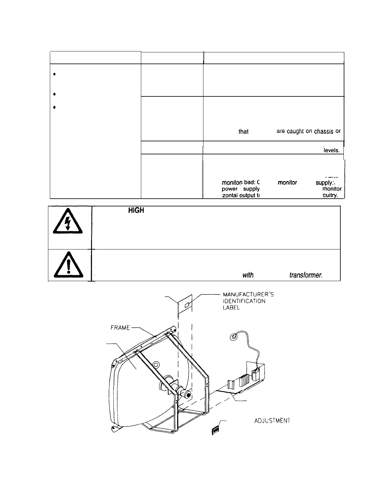
CRT
*NECK BOARD
-,@,,-
E;;$R-
’
I
*MAIN BOARD
ASSEMBLY
REMOTE
ADJUSTMEN
BOARD ASSEMBLY
Typical Monitor Components
7-l 0
10