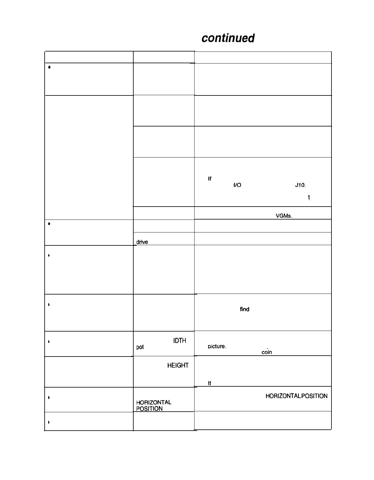
Video Troubleshooting Table, confinued
SYMPTOM CAUSE REQUIRED ACTION
.
White areas at screen edges
appear tinged with color
.
Dots at screen edges
appear ovoid or cylindrical
.
Video tears or rolls, or has
black bar down middle of
screen
.
Missing colors
.
One color is dimmer or
Maladjusted color
brfghter than others
bias pots
,
Whites appear tinted
everywhere on screen
.
Picture is dim or faded
,
Picture is too narrow
,
Picture is too short
,
Picture seems shifted to one
side
1
Keystone-shaped picture
Picture tube dynamic
convergence is out of
alignment
Faulty wiring
Faulty monitor
circuitry
Improper sync signals
Electromagnetic
fields
Faulty wiring
Faulty monitor color
drive
circuitry
Maladjusted
BRIGHTNESS pot or
subnormal picture
tube emission
Maladjusted W tDTH
Pot
Maladjusted HEtGHT
pot or-damaged
vertical circuit
Maladjusted
HORtZONTAL
POSITtON pot
Shorted turns in yoke
Have service bureau dynamically reconverge
monitor. This procedure requires removing and
repositioning yoke. Service bureau must follow
instructions from monitor manufacturer.
1. Check connectors and cables for wiring
continuity. Video cables connect graphics card
to circuit boards, and then to video monitor.
2. Assure connection of all cabinet ground wires,
especially at video monitor chassis.
1.
Verify that video monitor operates correctly by
connecting it to working VGM.
2.
Assure that video monitor is correct type for this
VGM. Video monitors with wrong resolution can’t
lock sync.
1.
Check to see if Video Board puts out type of
sync that your monitor requires.
2.
Verify that jumpers are set correctly for monitor.
3.
If necessary, add or remove video sync jumper
at Sound f/O Board jumper block JIO. With no
pins connected (or pins 2 and 3 connected),
board outputs positive sync. With pins
1.
and 2
connected, board outputs negative sync.
Move cabinet far away from machines,
appliances, or competitors’ VGMs.
Check connectors and cables for wiring
continuity from circuit boards to video monitor.
Verify that video monitor operates correctly by
connecting it to working VGM.
1.
Turn on VGM.
2. Enter Monitor Tests Menu.
3. Watch Color Bars screen in mirror.
4. Adjust three bias pots for best colors. (Most
monitor neck boards include these pots.)
5. Also check White Screen. Touch up controls.
6.
If whites still seem tinted, have service bureau
rejuvenate picture tube.
1.
Watch Color Bars screen. Adjust BRIGHTNESS
and CONTRAST pots for greatest number of
grays. You’ll
find
these pots on Monitor Remote
Control Board, behind coin door.
2. If pots have no effect, have service bureau
rejuvenate picture tube.
Enter Monitor Tests Menu. Watch Crosshatch
Screen while adjusting WIDTH pot for best
oicture.
You’ll find this pot on Monitor Remote
Control Board, behind cdin door.
1. Enter Monitor Tests Menu. Watch Crosshatch
Screen while adjusting HEIGHT pot for best
picture. You’ll find this pot on Monitor Remote
Control Board, behind coin door.
2.
If pot has no effect, service vertical output circuit.
Enter Monitor Tests Menu. Watch Crosshatch
Screen while adjusting HORtZONTAL POStTlON
pot for best picture. You’ll find this pot on Monitor
Remote Control Board, behind coin door.
1. Substitute working yoke.
2. Have service bureau converge monitor.
3. Retest monitor.
7-12
12