CPU BOARD ASSEMBLY
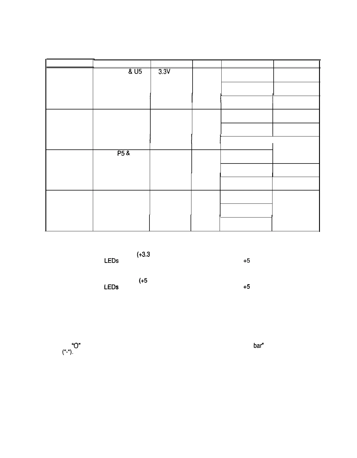
LED INDICATOR STATUS CHART
DESIGNATION
LED 1
(NOTE 1)
LED 2
(NOTE 2)
LED 3
(NOTE 3)
LED 4
(NOTE 4)
LOCATION
NEAR Cl
&
U5
FUNCTION COLOR
STATE MEANING
3.3v
CPU
RED
OFF INSUFFICIENT
POWER
POWER
INDICATOR
ON POWER O.K.
I
I
BLINKING
I
POWER
FAULT
NEAR C24 & U6 5v CPU RED
OFF INSUFFICIENT
POWER
POWER
INDICATOR
ON
POWER O.K.
I
I
BLINKING
I
POWER
FAULT
NEAR
P5
&
U28 HARD DISK GREEN OFF
NOT IN USE
DRIVE
ACTIVITY
ON
LOCKED UP
BLINKING NORMAL DISK
ACTIVITY
NEAR U22 & U26
CPU
RED OFF* *SEE NOTE
ACTIVITY
4 BELOW
INDICATOR
ON*
BLINKING*
SEQUENTIALLY
NOTES:
1.
LED 1 monitors CPU power
(+3.3
Volts). If this LED is off or blinking, investigate the processor
circuits. If other LEDs are off or blinking at the same time, check the +5 Volt circuits or the game
power supply.
2.
LED 2 monitors CPU power
(+5
Volts). If this LED is off or blinking, investigate the processor
circuits. If other LEDs are off or blinking at the same time, check the +5 Volt circuits or the game
power supply.
3.
LED 3 flashes when the hard disk is operating during game play. It may light continuously during
startup. If this LED is lighted continuously, there may be a fault with the hard disk drive, which may
be locked up.
4.
LED 4 initially indicates program start-up stages.
It is a seven segment alpha-numeric display
device. Under normal conditions, it displays a lowercase “b” or a sequentially blinking segments in
an
“0”
pattern. During any of the self-test screens, it displays a “bouncing bar” resembling a hyphen
(I‘-.).
6-6
 Loading...