DESlGNATlON
(NO&
1)
(N&E
3)
(NC%
2)
J4
(NOTE 4)
(NOTE 2)
J6
(NOTE 4)
J7
(NOTE 4)
J8
(NOTE 1)
NOTES:
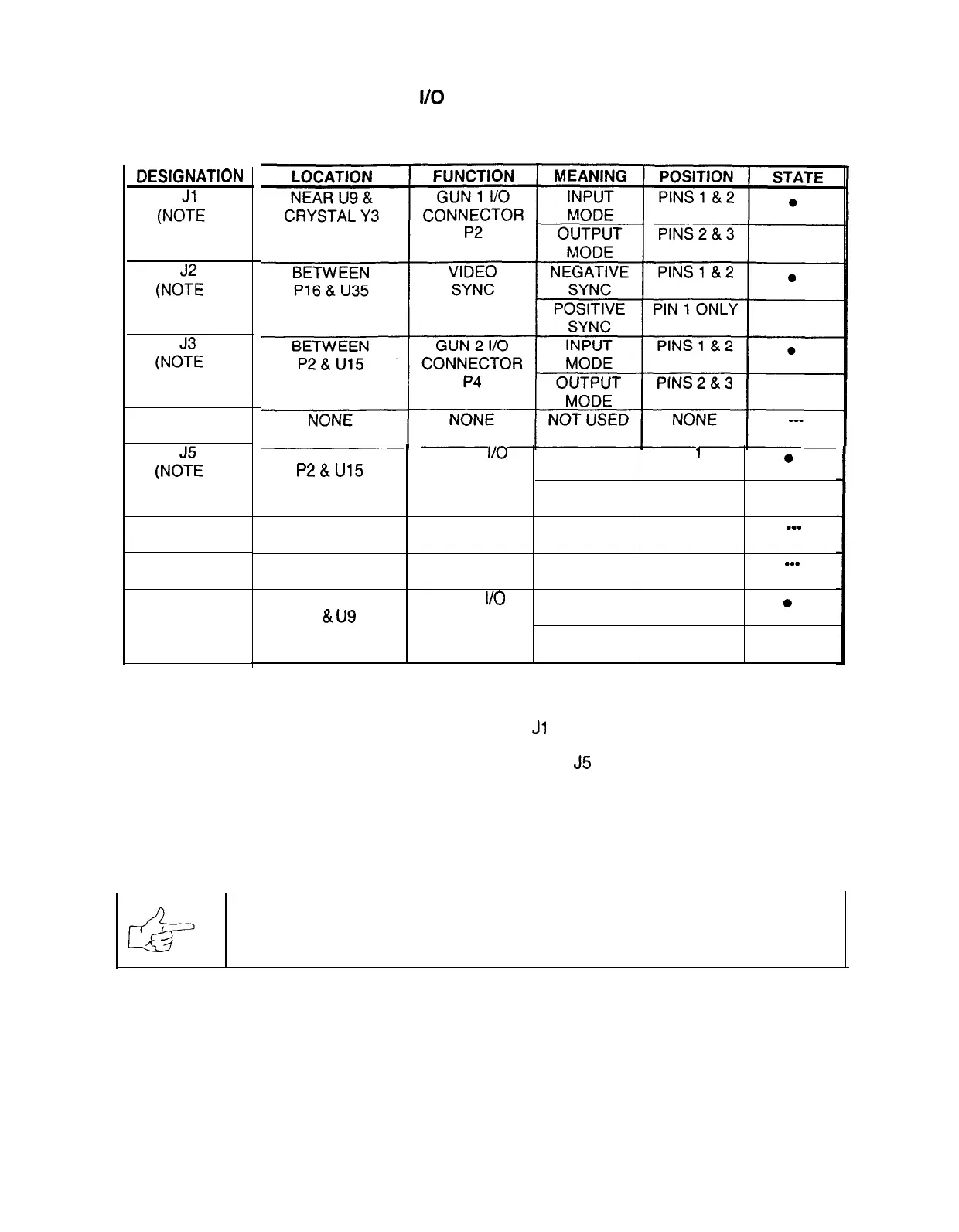
SOUND i/O BOARD ASSEMBLY
JUMPER POSITION CHART
BETWEEN
P2&U15
NONE
GUN 2
I/O
INPUT
PINS
1
& 2
0
CONNECTOR MODE
P4
OUTPUT
PINS 2 & 3
MODE
NONE NOT USED NONE
___
NONE NONE NOT USED
NONE
___
BETWEEN
P4
&
u9
GUN 1
I/O
INPUT
PINS 1 & 2
0
CONNECTOR MODE
P2
OUTPUT
PINS 2 & 3
MODE
1.
Select the Gun 1 (P2) I/O port mode by setting both the
Jl
and J8 jumpers to input or output mode.
2. Select the Gun 2 (P4) I/O port mode by setting both the J3 and
J5
jumpers to input or output mode.
3.
Set the Video Sync Signal Polarity to Positive by setting the J2 jumper on pin 1 only. Do not remove.
4.
These jumpers are not required for this game. They may not be present on the board assembly.
NOTICE: The manufacturer wants you to know that guns are not supplied
with this game.
Connectors are provided for other games that do have guns. We regret your disappointment.
6-8
8