Warlords
TM
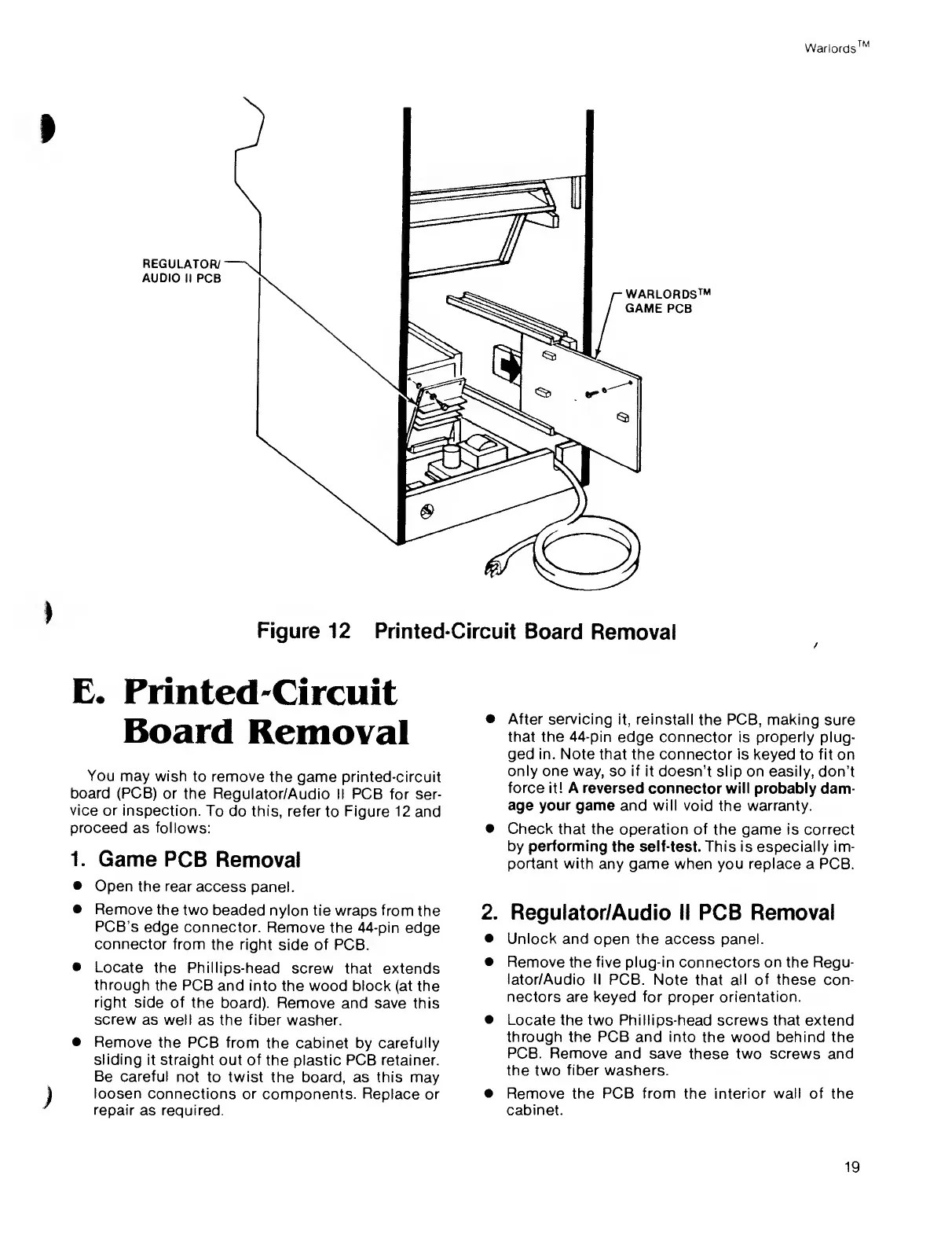
Figure 12
Printed-Circuit
Board
Removal
E.
Printed-Circuit
Board
Removal
You
may wish
to
remove
the
game printed-circuit
board (PCB)
or the
Regulator/Audio II PCB for
ser-
vice or
inspection.
To do this, refer
to Figure 12 and
proceed
as follows:
1.
Game PCB
Removal
•
Open the rear
access
panel.
•
Remove
the two
beaded
nylon tie wraps from the
PCB’s
edge
connector.
Remove the 44-pin
edge
connector
from the
right
side
of PCB.
•
Locate
the
Phillips-head
screw that extends
through
the PCB
and into
the
wood block
(at the
right
side of
the board).
Remove and save this
screw
as well
as the fiber washer.
•
Remove
the PCB from
the cabinet by carefully
sliding
it straight
out of the plastic PCB retainer.
Be careful
not to twist
the board, as
this
may
loosen
connections or
components. Replace or
repair
as required.
•
After servicing
it, reinstall
the PCB,
making
sure
that the 44-pin
edge connector is properly
plug-
ged in. Note that the
connector is keyed
to
fit on
only one way,
so
if it
doesn’t slip on easily, don’t
force it! A
reversed connector
will
probably dam-
age your game
and
will
void the warranty.
•
Check that
the operation of
the
game
is correct
by performing
the self-test. This is especially im-
portant with
any game when you
replace
a PCB.
2.
Regulator/Audio II PCB Removal
•
Unlock
and open the access panel.
•
Remove the five plug-in
connectors
on the Regu-
lator/Audio II
PCB. Note
that
all of these con-
nectors are keyed for
proper
orientation.
•
Locate
the two Phillips-head screws that extend
through the PCB and into
the wood
behind
the
PCB. Remove
and
save
these two screws and
the two
fiber
washers.
•
Remove the PCB from
the
interior wall of the
cabinet.
19