15
EN
WALL MOUNTED INSTALLATION
-The power supply must be directly connected to the household
power system after the double-pole circuit breaker in accordance
with installation rules.
-If the power cable is damaged, it must be replaced by the manufacturer,
its customer service or similar qualied persons in order to avoid any
risks.
-If you use the pilot wire and it is protected by a 30mA residual-
current circuit breaker (e.g. bathroom), the pilot wire power must be
protected on this residual-current circuit breaker.
-If you want to use a load-shedding device, choose one with a pilot
wire outlet rather than one with power outlet, so as not to damage
the thermostat.
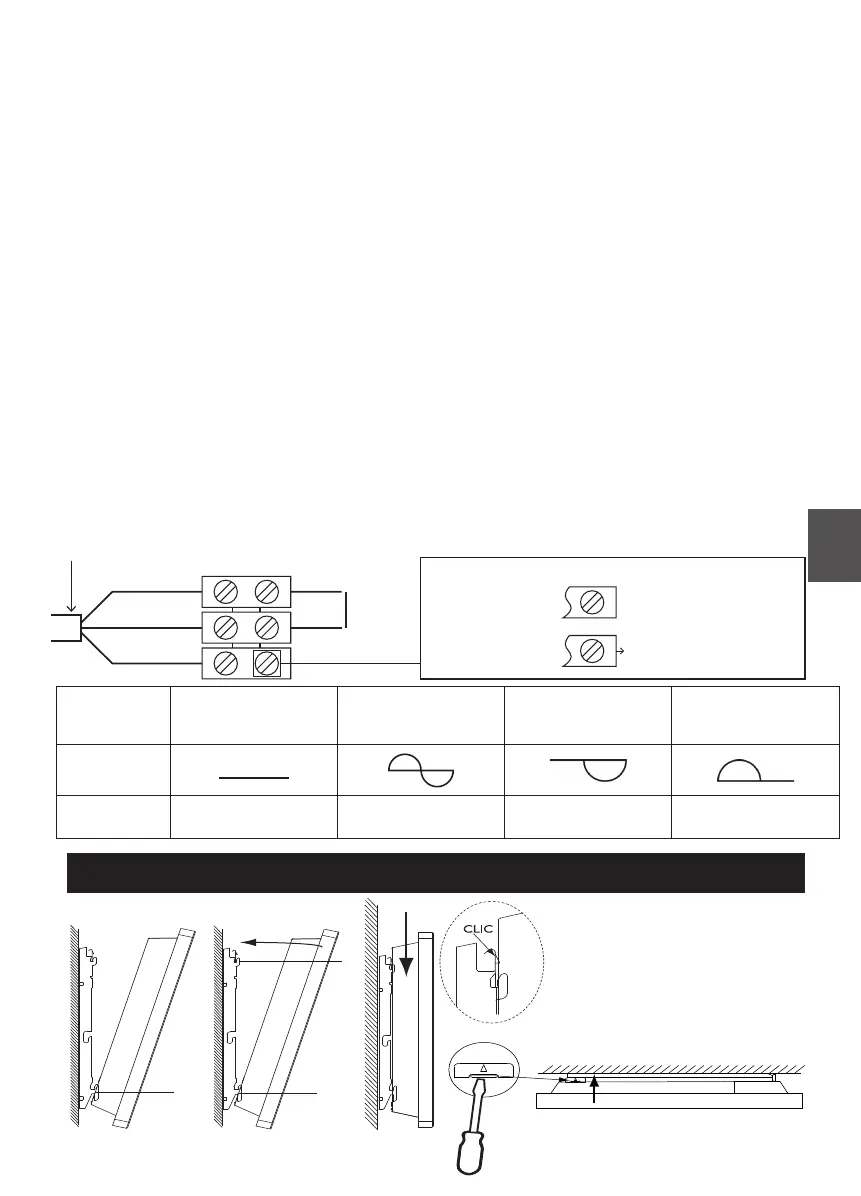
Device Wiring Diagram
-Turn off the power and connect the wires according to the following
diagram:
Neutral = Blue
Phase = Brown
Panel heater cable
Phase
Neutral
Electricity
grid
1
st
case: One heater
2
nd
case: Multiple heater
Unpiloted device
Pilot wire not connected
To devices with reception box
or central programming
2 possible cases:
Commands
Received
No current
Complete
altermation
230 V
Negative
Half/altermation
– 115V
Positive
Half/altermation
+ 115V
Oscilloscope
Ref/Neutral
Mode
obtained
COMFORT ECO ANTI - FREEZE
STOP HEATING
LOAD SHEDDING