♦
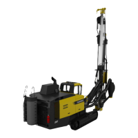
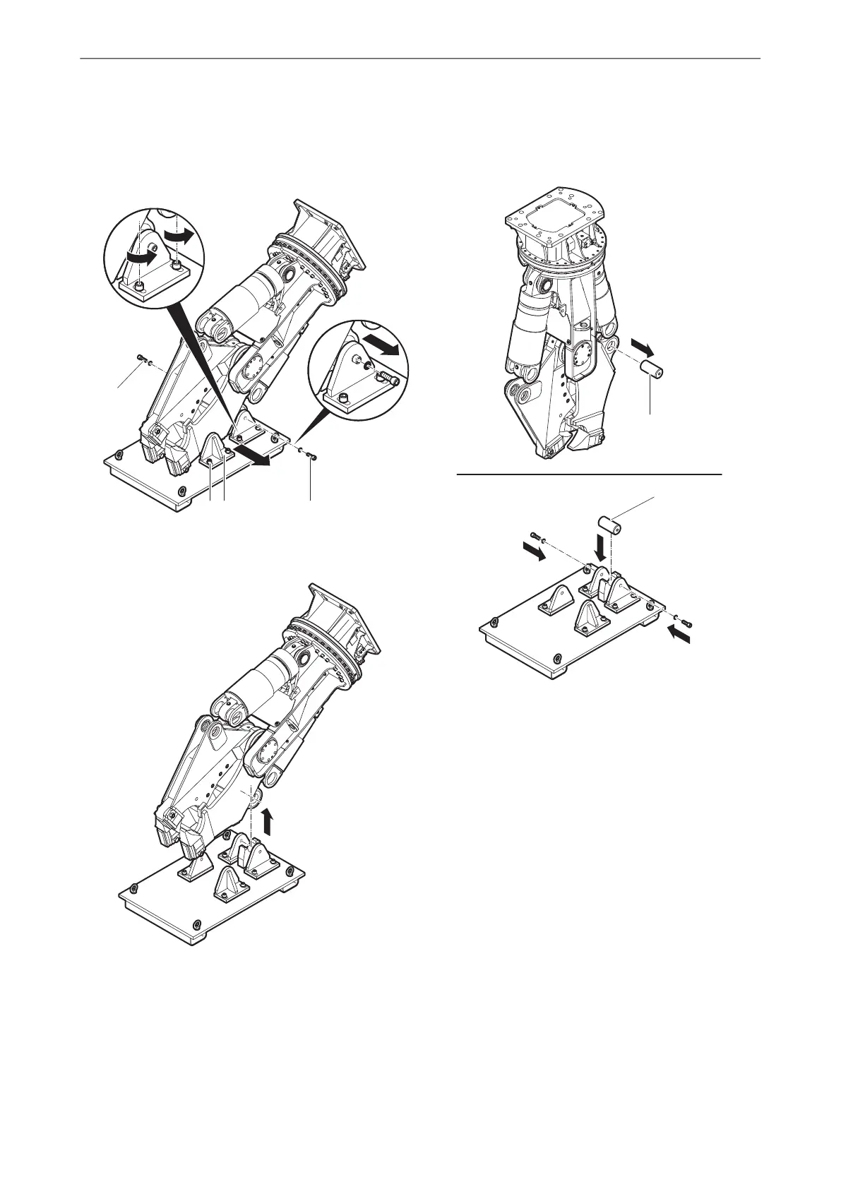
Loosen all Allen screws (I) at the holders (G) of
the assembly rack.
♦
Disassemble the Allen screws (H,J) from the pin
of the assembly rack.
♦
Pull the holders apart.
♦
Lift the hydraulic demolition cutter.
♦
Pull the bolts (F) out of the cylinder pin bearing of
the cutter jaw (double).
♦
Fit the bolts (F) in the assembly rack semi-shell
and tighten all the Allen screws of the empty
assembly rack to prevent loss of parts.
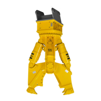
♦
Let the hydraulic demolition cutter hang vertically
on the carrier, do not place it on the ground.
♦
Extend the hydraulic cylinders.
♦
Secure the carrier such that it cannot move
unexpectedly.
♦
Align the drilled holes for the cylinder pins (D).
♦
Fit the cylinder pins (D).
♦
Fit the spacer rings (E).
♦
Fit the covers (C).
♦
Fit a pair of lock washers (R) onto every Allen
screw (S).
♦
Secure the covers (C) by fitting the Allen screws
(S).
33© 2015 Construction Tools GmbH | No. 3390 5141 01 | 2015-11-16
Original instructions
INSTALLATIONCC 1700 U, 1700 S
 Loading...