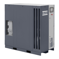
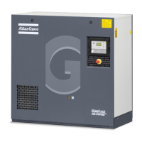
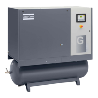
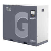
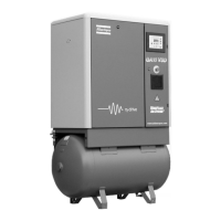
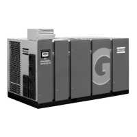
97
Instruction book
9096 3321 00
Description
1 Minimum free area to be reserved for the compressor installation
2 Ventilation proposals (on air-cooled compressors)
3 Cooling systems (on water-cooled compressors)
1 Install the compressor unit on a solid, level floor suitable for taking the weight.
2 Position of the compressed air outlet valve.
The maximum total pipe length (including interconnecting piping between compressor and receiver) can
dp = (L x 450 x Qc
1.85
) / (d
5
x p)
d = Inner diameter of the outlet pipe in mm
dp = Pressure drop (recommended maximum = 0.1 bar)
L = Length of outlet pipe in m
p = Absolute pressure at the compressor outlet in bar(a)
Qc = Free air delivery of the compressor in l/s
Ventilation: the inlet grids and ventilation fan should be installed in such a way that any recirculation of
cooling air to the compressor or dryer is avoided. The maximum air velocity through the grids is 5m/s.
The maximum air temperature at the compressor intake is 46 °C (minimum 0 °C).
For air-cooled
compressors ventilation alternatives 1 and 3, the ventilation capacity required to limit the
Qv = 1.06 N/dT for GA Workplace compressors
Qv = (1.06 N + 8)/dT for GA Workplace Full-Feature compressors
The cooling air of the dryer can be ducted outside
Qv= Required ventilation capacity in m
3
/s
N = Shaft input of compressor in kW
dT = Temperature increase in compressor room in °C
For ventilation alternatives 2 and 4:
the fan capacity should match the compressor fan capacity at a
pressure head equal to the pressure drop over the air ducts.
For water-cooled compressors, the ventilation capacity required to limit the compressor room
temperature can be calculated from:
Qv = 0.13 N/dT for GA Workplace compressors
Qv = (0.13 N + 8)/dT for GA Workplace Full-Feature compressors
Max. allowable pressure drop in ducting before or after the compressor = 30 Pa
5 The drain pipes to the drain collector must not dip into the water of the drain collector. Atlas Copco has
oil/water separators (type OSD or OSCi) to separate the major part of the oil from the condensate to
ensure that the condensate meets the requiremen
6 Control module with monitoring panel.
Power supply cable to be sized and installed by a qualified electrician.
To preserve the protection degree of the electric cubicle and to protect its components from dust from
the environment, it is mandatory to use a proper cable gland when connecting the supply cable to the
8 Provision for energy recovery system.
9 Filter, type DD for general purposes. The filter traps solid particles down to 1 micron with a max. oil
carry-over of 0.5 mg/m
3
. A high-efficiency filter, type PD, maybe installed downstream of a DD filter.
This filter traps solid particles down to 0.01 m
10 Safety valve
3
4
7
 Loading...

