13
2920 1190 05
Instruction book Industrial Air Division
1.4.2.3 Function keys
Abbre- Desig- Function
viation nation
Add Add To add compressor start/stop commands (day/
hour)
Canc Cancel To cancel a programmed setting when
programming parameters
Del Delete To delete compressor start/stop commands
Lim Limits To show limits for a programmable setting
List List To list programmed start/stop commands
(day/hour)
Main Main To return from a menu to the main display
(Fig. 7b)
Menu Menu Starting from the main display (Fig. 7b), to
initiate the main menu (Fig. 7c) which gives
access to submenus
Starting from a submenu, to return to the main
menu (Fig. 7c)
Mod Modify To modify programmable settings
More More To have a quick look at the compressor status
Prog Program To program modified settings
Rset Reset To reset a timer or message
Rtrn Return To return to a previously shown option or
menu
Slct Select To select a submenu or to read more details
of a selection shown on display
1.5 Electric cabinet (Figs. 8)
The cabinet comprises electric components such as the start
and speed regulation unit of the motor (U1), a transformer (T1)
and fuses (F1/F4) as well as the start contactor (K15) for the
fan motor. A fan motor circuit breaker (Q15) is also provided.
If it should be necessary to change the rotation direction of the
fan motor (M2-Figs. 2), switch off the voltage and reverse two
connections at the terminals of circuit breaker (Q15).
The parameters of the start and speed regulation unit (U1) are
factory-set and need no adjustment. Changing parameters may
damage the compressor; consult Atlas Copco.
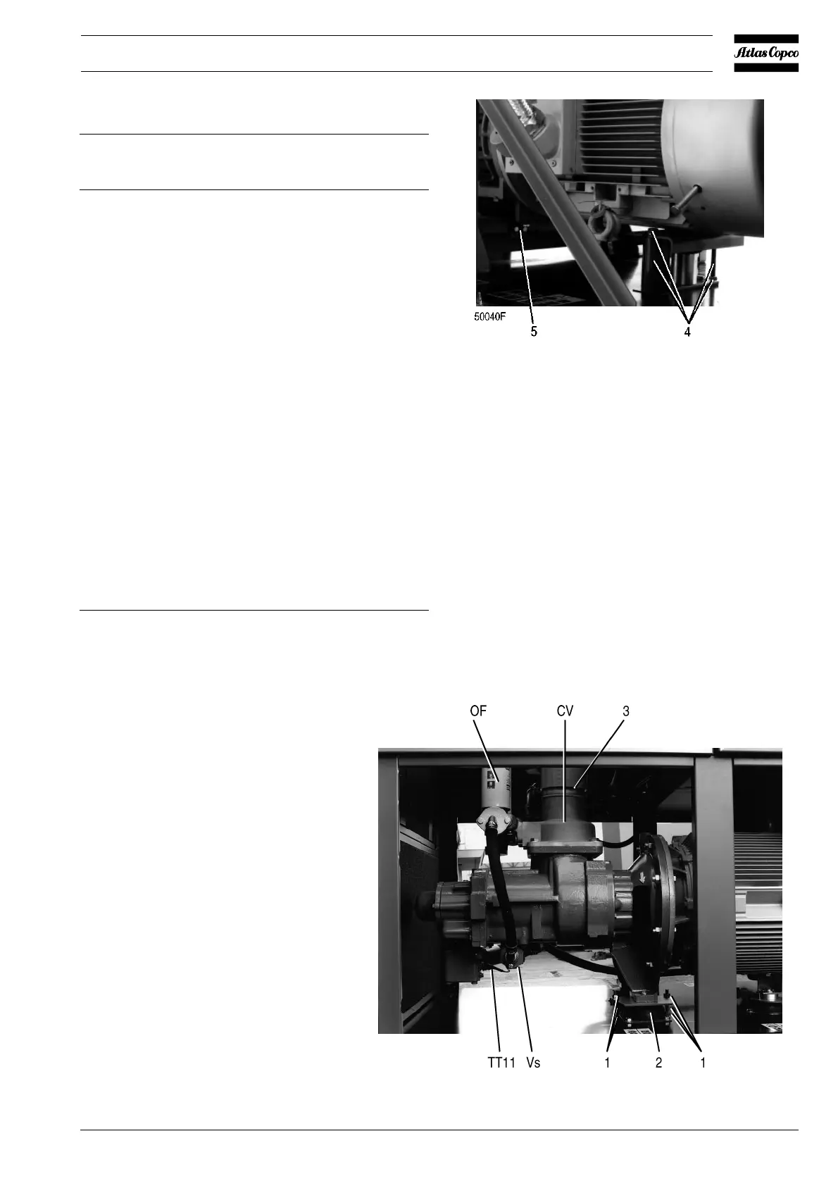
Fig. 9b. Transport bolts of GA90 (W) VSD
Fig. 9a. Transport bolts of GA50 VSD
CV. Check valve
OF. Oil filter
TT11. Temperature sensor, compressor
element outlet
Vs. Oil stop valve
1. Studs and nuts (to be removed)
2. Vibration damper
3. Hose clip, air inlet hose
4. Studs and nuts (to be removed)
Figs. 9. Transport bolts
F006
 Loading...