Selector EN Product Instructions
© Atlas Copco Industrial Technique AB - 9836 1733 02
5
8. Repeat the procedure for every socket you are going to use.
9. Replace the socket holders in the order you want to have your P-sets. See P-set Order.
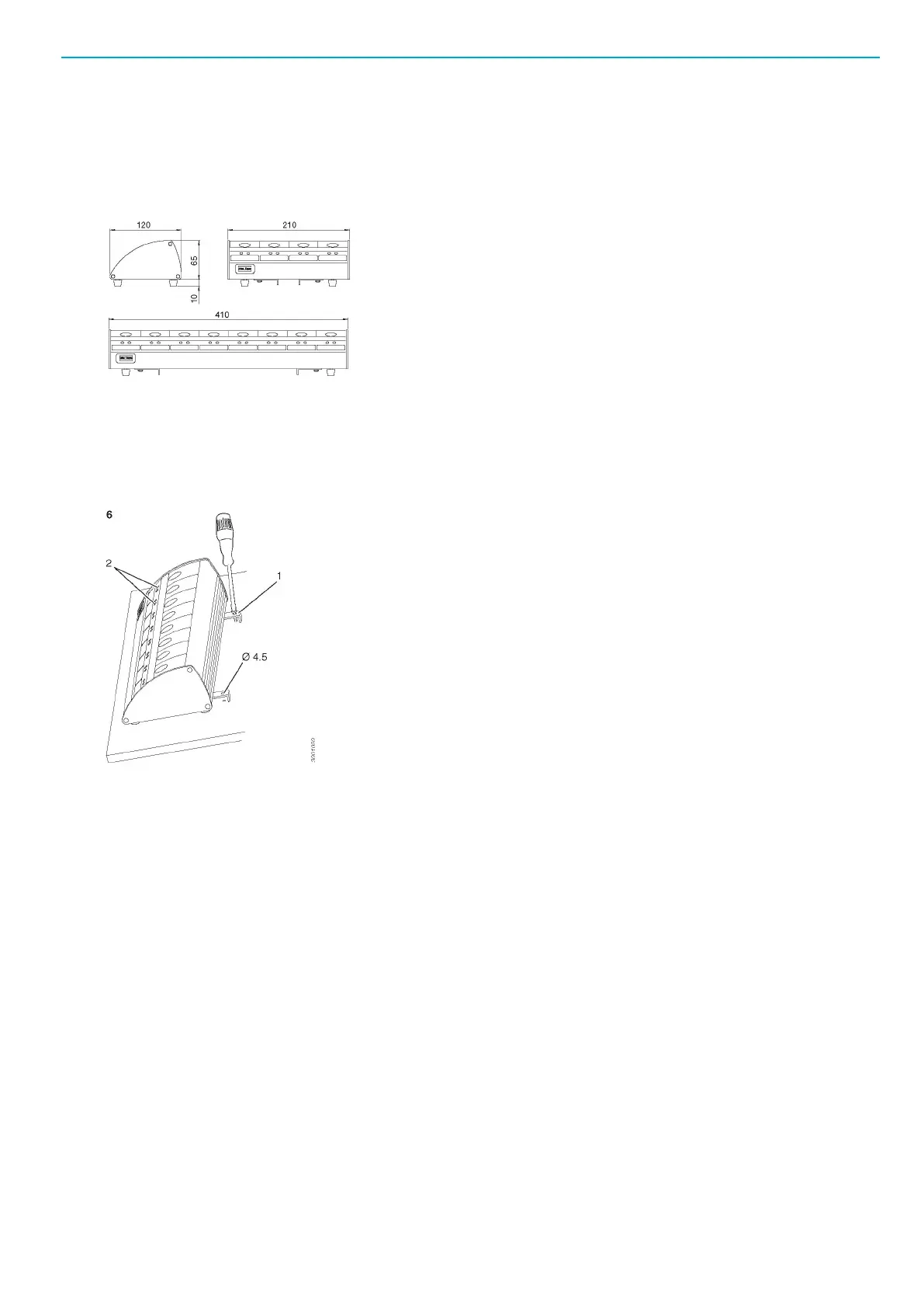
Dimensions
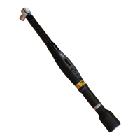
Mounting
Find a spot to mount the Selector on. It is recommended that you use the mounting brackets, 1, and fix-
ture it to the surface. Place it so it is possible to see the indicator positions, 2, next to each socket. Screw
size 4 mm.
Connectors and cables
On the Selector there are two connectors for the I/O Bus. Both of these has to be connected. The drive is
also equipped with two connectors for the I/O -Bus, which have to be connected as well. Every connector
in the system has to be connected , either by a cable, 4222 0470, or a termination, 4222 0443 00. The fig-
ure shows how the I/O-bus accessories shall be connected.