EasyManua.ls Logo

Atlas Copco XAMS 407 CD User Manual

Atlas Copco XAMS 407 CD
88 pages
To Next Page IconTo Next Page
Page #1 background imageLoading...
Page #1 background image
XAMS 407 CD - XAMS 850 CD7
XATS 377 CD - XATS 800 CD7
XAHS 347 CD - XAHS 710 CD7
XAVS 307 CD - XAVS 650 CD7
Instruction Manual For Portable Compressors
English
Engine CAT C7

Table of Contents

Question and Answer IconNeed help?

Do you have a question about the Atlas Copco XAMS 407 CD and is the answer not in the manual?

Atlas Copco XAMS 407 CD Specifications

General IconGeneral
ModelXAMS 407 CD
Working Pressure7 bar
Number of cylinders4
CoolingAir-cooled
Drive TypeDirect drive
Power SupplyDiesel
TypeDiesel
EngineDeutz

Summary

Warranty and Liability Limitation

Safety precautions

INTRODUCTION

General introduction to the manual, emphasizing safe operation and product policies.

GENERAL SAFETY PRECAUTIONS

SAFETY DURING TRANSPORT AND INSTALLATION

SAFETY DURING USE AND OPERATION

SAFETY DURING MAINTENANCE AND REPAIR

TOOL APPLICATIONS SAFETY

SPECIFIC SAFETY PRECAUTIONS

Batteries

Safety measures for handling and servicing batteries, including charging and electrolyte.

Pressure vessels

Maintenance and installation requirements for pressure vessels.

Safety valves

Operating and maintenance guidelines for safety valves.

Leading particulars

GENERAL DESCRIPTION

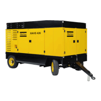
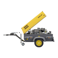
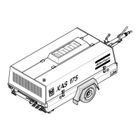
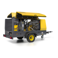
Overview of the compressor models, engine type, and key systems.

Main Parts

COMPRESSOR REGULATING SYSTEM

OVERVIEW

Diagram and explanation of the compressor regulating system.

AIR FLOW

OIL SYSTEM

CONTINUOUS REGULATING SYSTEM

ELECTRIC SYSTEM

MARKINGS AND INFORMATION LABELS

Operating instructions

PARKING, TOWING AND LIFTING INSTRUCTIONS

Instructions for parking, towing, and lifting the compressor safely.

PARKING INSTRUCTIONS

Detailed steps for parking the compressor correctly.

TOWING INSTRUCTIONS

HEIGHT ADJUSTMENT

LIFTING INSTRUCTIONS

STARTING / STOPPING

BEFORE STARTING

Pre-operation checks and procedures before starting the compressor.

BATTERY SWITCH

CONTROL PANEL

XC2002TM MODULE

Description of the XC2002TM module and its functions.

Pushbutton and LED functions

Explanation of the pushbuttons and LED indicators on the control panel.

XC2002TM MENU OVERVIEW

Parameter list

Language

Icons

Extra views display

Fuel pressure

Shows fuel pressure and running hours.

Fuel consumption

Shows engine fuel consumption and running hours.

Air Inlet temperature

Regulating pressure

Vessel pressure

Compressor element temperature

XC2002 TM MENU DESCRIPTION

Status Display (pop-up window)

Displays status information in a pop-up window when active.

Alarm Display (pop-up window)

Displays active alarms in a pop-up window.

List of possible alarms:

DURING OPERATION

OPERATIONS OVERVIEW

Explains local, remote, and PC control modes for the compressor.

POWER ON / OFF

STARTING

WARMING UP

LOADING

STOPPING

EMERGENCY STOP

FAULT CODES

Maintenance

LIABILITY

Manufacturer's disclaimer regarding non-original parts and modifications.

SERVICE PAKS

Collection of parts for specific maintenance tasks to minimize downtime.

Use of service paks

Benefits of using service paks for genuine parts and reduced downtime.

SERVICE KITS

Collection of parts for specific repair or rebuilding tasks to improve uptime.

STORAGE

Instructions for storing the compressor, including regular runs.

PREVENTIVE MAINTENANCE SCHEDULE FOR THE COMPRESSOR

OIL SPECIFICATIONS

ENGINE OIL

OIL LEVEL CHECK

CHECK ENGINE OIL LEVEL

Procedure for checking engine oil level as per engine manual.

CHECK COMPRESSOR OIL LEVEL

Procedure for checking compressor oil level using the gauge.

OIL AND OIL FILTER CHANGE

ENGINE OIL AND OIL FILTER CHANGE

Refer to Preventive Maintenance Schedule for engine oil filter change.

COMPRESSOR OIL AND OIL FILTER CHANGE

Step-by-step guide for changing compressor oil and filters.

TOPPING UP THE COMPRESSOR OIL

COOLANT SPECIFICATIONS

PARCOOL EG

PARCOOL EG Concentrate

HANDLING PARCOOL EG

COOLANT CHECK

Visual check

Inspect coolant color and for particles.

pH measurement

Check coolant pH value using a pH meter.

Glycol concentration measurement

Measure glycol concentration for engine protection.

TOPPING UP/REPLACING COOLANT

Instructions for topping up or replacing the coolant.

TOPPING UP WITHOUT DRAINING FROM THE COOLING SYSTEM

TOPPING UP AFTER LIMITED QUANTITY DRAINING FROM THE COOLING SYSTEM

REPLACING THE COOLANT

Drain

Procedure for draining the cooling system and disposal.

Flush

Instructions for flushing the cooling system with clean water.

Fill

Procedure for filling the cooling system with coolant mixture.

CLEANING COOLERS

BATTERY CARE

ELECTROLYTE

Safety instructions for handling battery electrolyte.

ACTIVATING A DRY-CHARGED BATTERY

Steps to activate a dry-charged battery.

RECHARGING A BATTERY

Procedure for charging a battery correctly.

BATTERY MAINTENANCE

Tips for keeping batteries clean, dry, and terminals tight.

COMPRESSOR ELEMENT OVERHAUL

Adjustments and servicing procedures

ADJUSTMENT OF THE CONTINUOUS REGULATING SYSTEM

Procedure for adjusting the continuous regulating system pressure.

AIR FILTER ENGINE/COMPRESSOR

SERVICING

General servicing advice for air filters, recommending replacement over cleaning.

CLEANING THE DUST TRAP

Daily procedure to remove dust from the dust trap.

CLEANING INSTRUCTIONS FILTER ELEMENT

Guidelines for cleaning filter elements if necessary, with warnings.

REPLACING THE AIR FILTER ELEMENT

AIR RECEIVER

SAFETY VALVE

Following checks must be carried out on the safety valve (2)

Checks for safety valve lifting gear and set pressure.

FUEL SYSTEM

PRIMING INSTRUCTIONS

Procedure to prime the fuel system for starting.

DRAINING INSTRUCTIONS

Replacing the filter elements: (to be updated)

BRAKE ADJUSTMENT

BRAKE SHOE ADJUSTMENT

Detailed steps for adjusting brake shoes on the compressor.

AUDIT PROCEDURE OF BRAKE CABLE ADJUSTMENT

BRAKE CABLE ADJUSTMENT

TEST PROCEDURE OF BRAKE CABLE ADJUSTMENT

Problem solving

Problem: Compressor capacity or pressure below normal.

Troubleshooting for low compressor capacity or pressure.

Problem: Pressure in air receiver rises above maximum and causes safety valve to blow.

Problem: After working some time, the unit stops through a shutdown switch.

Problem: Air and oil mist expelles from air filters immediately after stopping.

Problem: Compressor overheating.

Alternator precautions

Precautions when working with the alternator and battery connections.

Available options

Support

Rigid support version for rough conditions, mountable on trucks.

Fix height towbar with brakes

Fixed towbar with integrated parking brake.

Adjustable height towbar with brakes

Dual-hinged articulating towbar with integrated parking brake.

DIN/NATO/ITA eye

Towing eye options according to DIN, NATO, or ITA specifications.

Road signalization

Road signalization option compliant with European regulations for rear lights.

Road signalization USA

Additional side mounted lights for North American road signalization.

SCANDIC cold weather package (to -10°C)

Cold weather package with engine heater plug and approved vessel.

NORDIC cold weather package (-10°C to -25°C) - OTM only

Cold weather package with preheater and engine-independent water heater.

ARCTIC cold start package (-25°C to -30°C) - OTM only

Cold start package with electric engine preheater and insulation.

Aftercooler + Water separator

Reduces air temperature and includes aftercooler bypass.

Fine Filter (PD)

Removes particles and oil content down to 0.01 mg/m³.

Active Coalescing Filter (QD)

Additional oil vapour and odour filter for improved air quality.

Reheater

Spark arrestor

Inlet shutdown

Refinery package

Customer colour canopy (1 colour)

Customer colour canopy (2 colours)

Customer colour frame (1 colour)

COSMOS

FuelXpert

Technical specifications

GENERAL TORQUE VALUES

Recommended torques for general assembly applications.

CRITICAL TORQUE VALUES

Specific torque values for critical assemblies.

COMPRESSOR / ENGINE SPECIFICATIONS

REFERENCE CONDITIONS

Specifications under standard reference conditions.

LIMITATIONS

Operating limitations for the compressor models.

ALTITUDE UNIT PERFORMANCE CURVE

PERFORMANCE DATA

DESIGN DATA

Compressor element

Design data for the compressor element.

Engine

Design data for the Caterpillar C7 engine.

Compressor

Compressor dimensions with brakes and adjustable towbar

Physical dimensions of the compressor unit.

Dataplate

Legislation Size 2 LP

PARTS, SUBJECTED TO SIMPLE PRESSURE VESSEL DIRECTIVE 87/404/EC

Parts subject to simple pressure vessel directive.

PARTS, SUBJECTED TO CAT. I AND COVERED BY THE MACHINE DIRECTIVE 89/392/EC

PARTS, SUBJECTED TO ART. I, PARAGRAPH 3.3

Disposal

GENERAL

Atlas Copco's policy on environmental effects and recycling.

DISPOSAL OF MATERIALS

Instructions for disposing of contaminated substances and materials.

Maintenance Log

Related product manuals