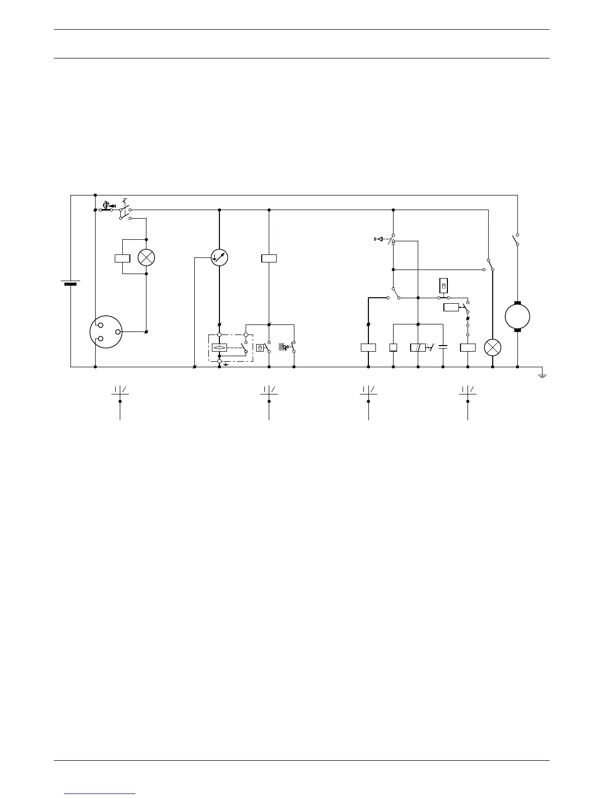
B6 Engine fuel level sensor/shut-down switch
C1 Suppressor
F1 Circuit breaker (10A)
G1 Alternator
G2 Batteries
H1 Alternator charging indicator lamp
H6 Alarm lamp, shut-down switches
K0 Starter solenoid
K1 Shut-down relay, compressor temperature and engine oil
pressure
K6 Starter motor protection relay
K8 Shut-down relay, engine temperature, V-belt protection
and fuel level
M1 Starter motor
P1 Fuel level gauge
P3 Hour meter
S1 ON-OFF switch
S2 Override/start switch
S5 Engine oil pressure shut-down switch
S7 Compressor temperature shut-down switch
S14 Engine temperature shut-down switch
S15 V-belt protection shut-down switch
V1 Diode
X1 Plug
Y1 Engine stop solenoid
Fig. 2.4 Circuit diagram (Nr. 2920 1184 00)
 Loading...