INSTRUCTION MANUAL
27
5.6 BRAKE (= OPTION) ADJUSTMENT
Before jacking up the compressor, connect it to
a towing vehicle or attach a weight of minimum
50 kg to the towbar.
Before removing a brake cable, a strap must be passed
around the brake lever, in its downward position, and the
towbar.
This strap may only be removed after proper reinstallation of
the brake cables.
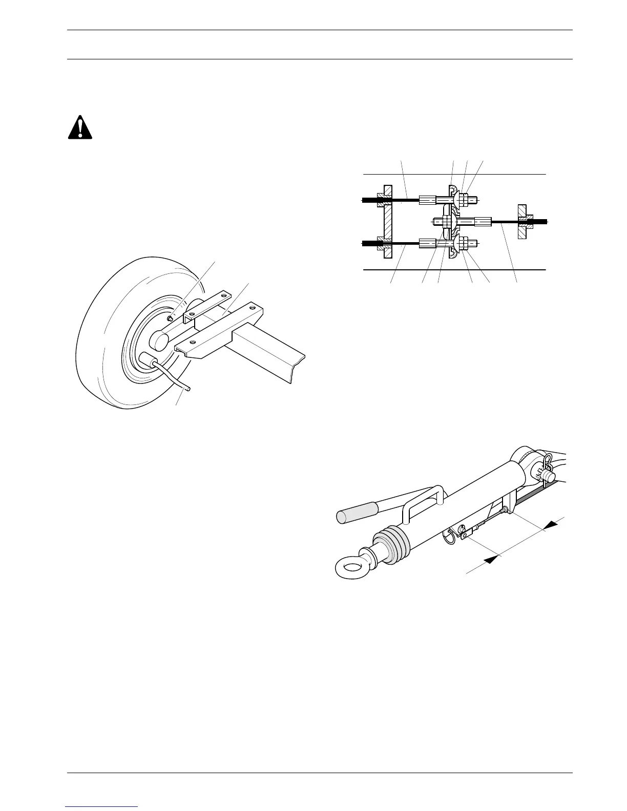
5.6.1 BRAKE SHOE ADJUSTMENT
Fig. 5.5 Wheel assembly
1 Adjusting nut, brake shoe
2 Axle
3 Brake cable
Brake shoe adjustment re-establishes the brake lining-to-drum
clearance and compensates for lining wear.
Adjustment can only be done with the towing eye in its pulled-
out position.
1. Jack up the axle until a wheel clears the floor. Support the
compressor on wooden blocks.
2. Disconnect the brake cables (Fig. 5.6, 1).
3. While turning the wheel in the sense of forward towing, turn
brake adjusting nut (Fig. 5.5, 1) clockwise until the brake
shoes block the drum. Then loosen the nut, with the wheel
again turning in the same direction, until the drum rotates
freely or with a light friction. Repeat for the other wheel.
4. Adjust the brake cables as described below.
5.6.2 BRAKE CABLE ADJUSTMENT
1. Reconnect the brake cables (Fig. 5.6).
2. With the towing eye pulled out and the hand brake lever
(Fig. 5.7) in the downward position, turn adjusting nut and
brake cable nuts (Fig. 5.6, 4) clockwise until there is no
slack in the brake mechanism.
The equalizer (Fig. 5.6, 6) must remain perpendicular to
main brake cable (Fig. 5.6, 5).
3. Apply the hand brake lever several times and repeat the
adjustment. Tighten the nuts with their lock nuts
(Fig. 5.6, 2). Remove the jack and the blocks.
4. Road-test the compressor and brake several times. Then
repeat steps 1 and 3 of Section 5.6.1.
Fig. 5.6 Brake cable arrangement
1 Brake cable
2 Lock nut
3 Adjusting nut
4 Brake cable nut
5 Main brake cable
6 Equalizer
5.6.3 TEST PROCEDURE OF BRAKE ADJUSTMENT
Fig. 5.7 Detail of brake system
The final check must be carried out as follows:
1. Check if the towing eye rod of the overrun brake
mechanism is in the outmost position.
2. Apply the handbrake lever.
3. Push the compressor a few inches backwards so that the
brake lever is automatically pulled further up.
4. Measure dimension ”A” (Fig. 5.7). The dimension ”A”
should be 197 mm (+/- 3 mm); if not, the brake mechanism
should be readjusted.
 Loading...