XA(S)175 Dd
26
5.2.4 REPLACING THE AIR FILTER ELEMENT
1. Release the snap clips (7) and remove the dust trap (6).
Clean the trap.
2. Remove retaining nut (5) and withdraw the element (3)
from housing (1).
If the element is to be serviced for immediate re-use,
reinstall the dust trap to protect the air intake system while
cleaning the element.
3. Replace the filter and reassemble in reverse order of
dismantling.
4. Inspect and tighten all air intake connections.
5. Reset the vacuum indicator (Fig. 5.3).
Fig. 5.3 Vacuum indicator
8 Air filter contamination indicator
9 Reset button
10 Yellow indicator
5.3 AIR RECEIVER
The air receiver is tested according to official standards.
Regularly have inspections carried out in conformity with local
regulations.
5.4 SAFETY VALVE
All adjustments or repairs are to be done by an
authorized representative of the valve supplier.
Following checks must be carried out:
– a check of the opening of the lifting gear, twice a year.
This can be done by screwing the cap of the valve anti-
clockwise.
– a check of the set pressure once a year according to the
local regulations. This check cannot be done on the
machine and must be carried out on a proper test bench.
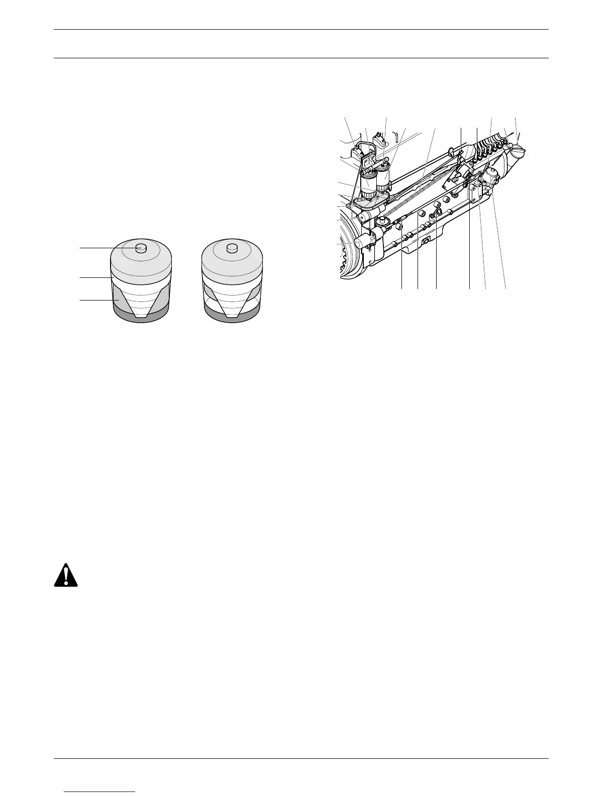
5.5 FUEL SYSTEM
Fig. 5.4 Fuel system
– Draining the filter(s)
Loosen the two vent plugs (VP1, VP2) and unscrew the drain
cocks (DC1, DC2) one or two turns. Close the cocks once the
water has been separated.
Operate the priming lever (10) on the fuel lift pump (FU) until
air-free fuel emerges at the released vent plugs.
Retighten the vent plugs.
– Replacing the filter(s)
1. Unscrew the filter(s).
2. Clean the adapter head sealing surface(s), lightly oil the
gasket(s) of the new filter(s) and screw it (them) onto the
header by hand. Next, securely tighten.
3. Air vent the fuel system and once the engine has been
restarted, check for fuel leaks.
– Air-venting the fuel system
Whenever air has entered the system, it is necessary to air-
vent, as otherwise the engine will either start with difficulty or
not at all.
Air-venting sequence
1. Vent plug (VP1)
2. Vent plug (VP2)
3. Vent screw (3) on injection pump
Operate the priming lever of the fuel lift pump until air-free fuel
issues from the vent points. If necessary, crank over the
engine shaft a little to obtain maximum stroke of the lift pump.
Operate the starting motor for a short time to air-vent the
injection lines if they have been removed. For full particulars,
consult the Engine Operation Manual.
 Loading...