4. Hardware User Guide
4.1. Microcontroller
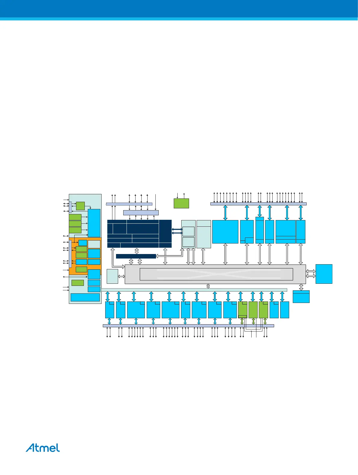
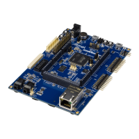
The SAME70-XPLD board is built around the ATSAME70Q21 in a 144-lead LQFP package. It is a low-
power ARM Cortex-M7 application microcontroller achieving high-performance computing device and
embedding a wide range of communication peripherals. It features a combination of user interface
functionalities and high data rate IOs, camera interface, 10/100 Ethernet ports, high-speed USB and SD
Card.
The ARM Cortex-M7 processor supports SDRAM memory through an EBI interface. An internal 150 MHz
multi-layer AHB bus architecture associated with 24 XDMA channels, 384 Kbytes of SRAM and 2048
Kbytes of Flash sustains the high bandwidth required by the microcontroller and the high-speed
peripherals.
Figure 4-1 SAM E70 Block Diagram
12-layer Bus Matrix
f
MAX
150 MHz
XDMA
PCK0..2
XIN32
XOUT32
ERASE
VDDIO
VDDOUT
Voltage
Regulator
TST
VDDIO
XIN
XOUT
VDDPLL
RTCOUT0
RTCOUT1
S M MMMS
S S S
S
MM
M
M
M
S
System Controller
SM
In-Circuit Emulator
MPU
Cortex-M7 Processor
f
MAX
300 MHz
NVIC
FPU
TPIU
ETM
16 Kbytes ICache + ECC16 Kbytes DCache + ECC
TCM
Interface
AXIM
AHBP
AHBS
AXI Bridge
TCK/SWCLK
TDI
TDO/TRACESWO
JTAGSEL
Serial Wire Debug/JTAG Boundary Scan
TRACECLK
TRACED0..3
TMS/SWDIO
NRST
PIOA/B/C/D/E
24-channel
XDMA
ROM
Boot
Program
Multi-port
SRAM
Flash
2048 Kbytes
1024 Kbytes
512 Kbytes
Flash
Unique ID
ITCM
DTCM
USBHS
Transceiver
External Bus Interface
Static Memory Controller (SMC)
SDRAM Controller (SDRAMC)
NAND Flash Logic
QSPI
XIP
DMA
ISI
GMAC
MII/RMII
5 x
UART
3 x
TWIHS
3 x
USART
2 x
PWM
2 x
12-bit
AFE
ACC
12-bit
DAC
PIO SSC HSMCI
2 x
SPI
4 x
TC
XDMA
DMA
Peripheral Bridge
URXD0..4
UTXD0..4
VREFN
CANRX0..1
CANTX0..1
RXD0..2
SCK0..2
RTS 0..2
TXD0..2
CTS 0..2
DSR0..2, DTR0 ..2
RI0..2, DCD0..2
ICM/SHA
PIODCCLK
PIODCEN1..2
PIODC0..7
TF
TK
TD
RD
RK
RF
MCDA0 ..3
MCCDA
MCCK
SPIx_NPCS 0..3
SPIx_MIS O
SPIx_MOSI
SPIx_SPC K
PWMCx_P WMH0..3
PWMCx_P WML0..3
PWMCx_P WMFI0..2
AFEx_ADTRG
AFEx_AD0..11
DAC0..1
DATRG
TWD0..2
TWCK0..2
2 x
MCAN
GTXCK, GRXCK, GREFCK
GCRS , G COL, GCRS DV
GMDC, G MDIO
GTS UCOMP
GRX0..3, GTX0 ..3
GRXER, GRXDV
GTXER, GTXDV
ISI_D[11 :0]
ISI_P CK, ISI_MCK
ISI_HS YNC, IS I_VSYNC
HSDP
HSDM
QMISO/QIO1
QMOS I/QIO0
QS CK, QCS
QIO2..3
A[23:0], D[15:0 ]
A21/NANDALE
A22/NANDCLE
NANDOE, NANDWE
A0/NLB, NUB
NWAIT, NCS 0..3, NRD, NWE
A16/S DBA0, A17/S DBA1
RAS, CAS , DQM0..1, S DCK, S DCKE, S DA10
DMA DMA
Temp Sensor
TIOB0..11
TCLK0..11
TIOA0..11
XDMA
XDMA
XDMAXDMAXDMAXDMAXDMA
XDMAXDMA
XDMA
FIFO
XDMA
TRNG
AES
DMA
VREFP
Backup RAM
1 Kbyte
TCM SRAM
System RAM
0–256 Kbytes
128–384 Kbytes
0–256 Kbytes
PMC
4/8/12 MHz
RC Oscillator
RSTC
SM
POR
SUPC
RTTRTC
WDT
UPLL
PLLA
3-20 MHz
Crystal
Oscillator
32 kHz
Crystal
Oscillator
32 kHz
RC Oscillator
Immediate Clear
256-bit SRAM
(GPBR)
Backup
RSWDT
4.2. Power Distribution
The SAME70-XPLD has two power sources as described in the figure Power Supply Block Diagram.
The kit can be powered from the EDBG USB or from the target USB. The kit automatically selects a
source to draw power. Priority is given to TARGET USB power input.
Atmel SAME70-XPLD [USER GUIDE]
Atmel-44050A-SAME70-XPLD_User Guide-12/2015
11