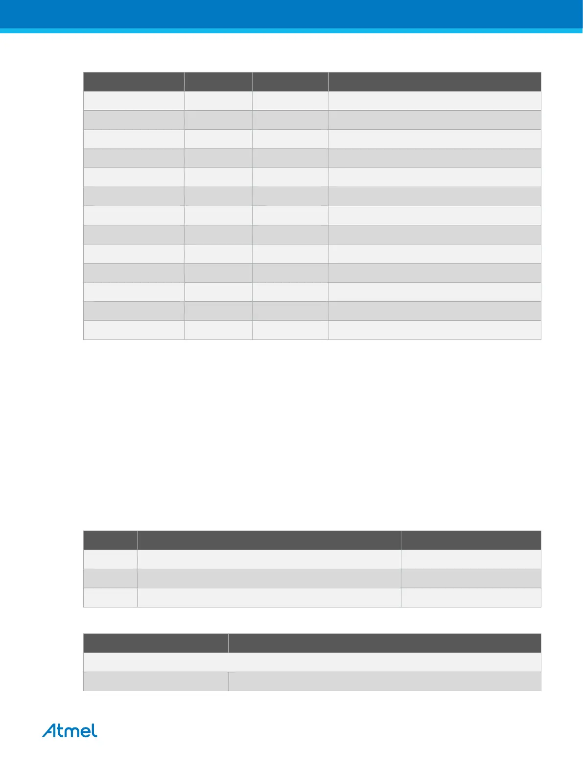
Table 4-13 CoreSight 20-Pin Trace Connector
Pin Number SAM E70 Pin Function Shared With
1-[VTREF] - VCC_3V3 --
2-[SWDIO] PB6 SWDIO Embedded Debugger
3-5-9-15-17-19[GND] - System Ground --
4-[SWCLK] PB7 SWCLK Embedded Debugger
6-[TRACESWO] PB5 TRACESWO Embedded Debugger
7-[KEY] - - --
8-11-13[NC] - - --
10-[nSRST] NRST NRST Arduino Connectors and Embedded Debugger
12-[TRACECLK] PD8 TRACECLK Ethernet
14-[TRACED0] PD4 TRACED0 Ethernet
16-[TRACED1] PD5 TRACED1 Ethernet
18-[TRACED2] PD6 TRACED2 Ethernet
20-[TRACED3] PD7 TRACED3 Ethernet
4.4. Peripherals
4.4.1. Clock Circuitry
The SAME70-XPLD board features three clock sources:
• Two crystals for the ATSAME70Q21 processor
• One crystal oscillator for the Ethernet MII/RMII chip
The crystals of the ATSAME70Q21 have cut-straps next to them that can be used to measure the
oscillator safety factor. This is done by cutting the strap and adding a resistor across the strap.
Information about oscillator allowance and safety factor can be found in the application note AVR4100;
information about clock calibration and compensation can be found in the application note AT03155.
Table 4-14 Main Components Associated with the Clock Systems
Quantity Description Component Assignment
1 Crystal for internal clock, 12 MHz XC301
1 Crystal for RTC clock, 32.768 kHz (Not Populated) XC300
1 Oscillator for Ethernet clock RMII, 25 MHz XC700
Table 4-15 External Crystals Connected on SAM E70
SAM E70 pin Function
32.768 kHz External Crystal Connection (Not Populated by default)
PA7 XIN32: Slow Clock Oscillator Input
Atmel SAME70-XPLD [USER GUIDE]
Atmel-44050A-SAME70-XPLD_User Guide-12/2015
30