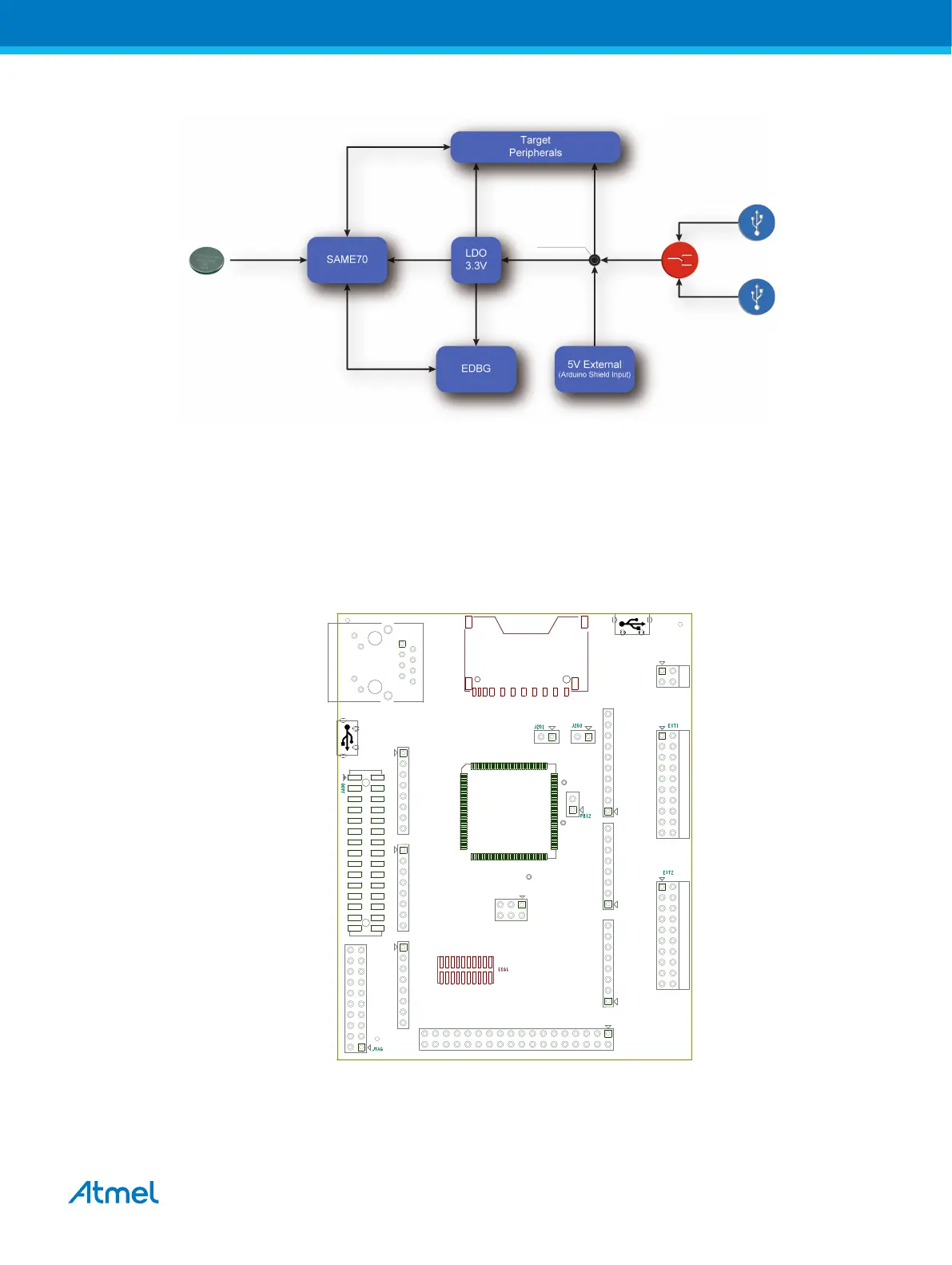
Figure 4-2 Power Supply Block Diagram
Coin Cell
TARGET USB
EDBG USB
VCC_5V0
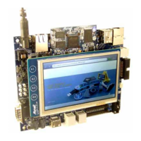
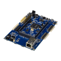
4.3. Connectors
These sections describe the implementation of all connectors and headers on SAME70-XPLD and their
connection to the ATSAME70Q21. The tables of connections in these sections also describe which
signals are shared between the headers and on-board functionality. The figure below shows all available
connectors and jumpers on the SAME70-XPLD.
Figure 4-3 SAME70-XPLD Connector Overview
J406 - SAME70 De bu g (SWD)
CAMERA
INTERFACE
J600 - SDCARD Socket
(Bottom Side )
J900
DEBUG USB
Co resight 20 - SWD + ETM
(Bottom Side )
J506 - SPI
J504 - An alog High J502 - Analog Low J501 - Powe r
J500 - Digital Hig hJ503 - Digital LowJ505 - Co mmunicat ion
J402 - Exte nsion Heade r 2 J401 - Exte nsion Heade r 1 J101 - Powe r He ader
VDDCORE VCC_MCU_3V3
J200 - ERASE
J700 - Ethern et RJ45
J507 - Digital Extra
J302
Ta rget USB
OPTIONOPTIONOPTION
OPTION OPTION OPTION
OPTION
OPTION
OPTION
Atmel SAME70-XPLD [USER GUIDE]
Atmel-44050A-SAME70-XPLD_User Guide-12/2015
12