Caution: Leaving J201 open while the main power source is present is to be avoided. This
would feed all power pins of the ATSAME70Q21 except VDDCORE, which may cause
permanent damage to the device.
4.3.7. Chip Erase Header
The chip erase header J200 is connected to the SAM E70 erase pin (PB12) and the main 3.3V. To erase
the contents of the SAM E70 flash memory, set a jumper on J200 and turn the power supply on. The
jumper can be removed soon after the power is on (flash erasing takes only 200ms). Using the chip erase
jumper is the only way to erase a chip with the security bit set.
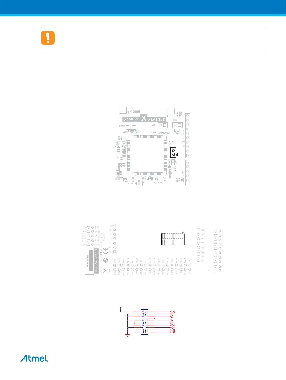
Figure 4-16 ERASE Chip Connector Placement J200
4.3.8. Trace Connector
ATSAME70Q21 supports 4-bit parallel trace. SAME70-XPLD implements a CoreSight 20 20-pin, 50-mil
connector footprint on PCB bottom side (not mounted by default).
Figure 4-17 Trace connector location on PCB
To use the trace functionality, an external debugger with trace support and CoreSight 20 pinout has to be
used. The table CoreSight 20-Pin Trace Connector shows the connections on the board.
Figure 4-18 CoreSight 20-Pin Trace Connector Schematic
SWDIO
SWCLK
TRACESWO
TRACECLK
TRACED0
TRACED1
TRACED2
TRACED3
VTREF
TRACE
VCC_3V3
PB6
PB7
PB5
PD8
TARGET_RESET
PD4
PD5
PD6
PD7
J403
CONN_HDR_10X2_19
DNP
1 2
3 4
65
8
9 10
11 12
13 14
15 16
17 18
19 20
Atmel SAME70-XPLD [USER GUIDE]
Atmel-44050A-SAME70-XPLD_User Guide-12/2015
29