J302 Pin Mnemonic Pin on SAM E70 SAM E70 Signal Name Signal Description
4 ID -- -- On-the-go identification
5 Ground GND GND System Ground
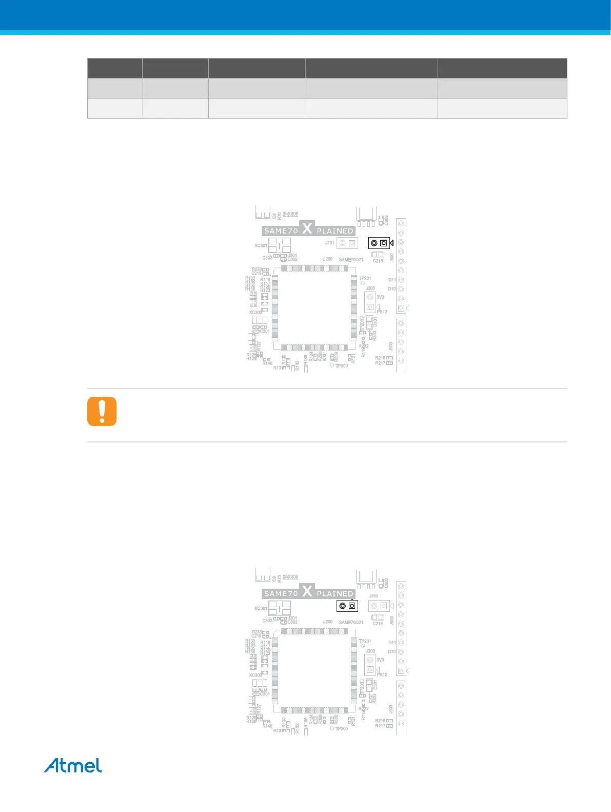
4.3.5. Current Measurement Header (VCC_MCU_P3V3 )
A 100mil pin-header marked "J203" is located at the upper edge of the SAME70-XPLD. All the power
going to the ATSAME70Q21 is routed through this header. To measure the power consumption of the
device, remove the jumper and replace it with an ammeter.
Figure 4-14 VCC_MCU_P3V3 Connector Placement J203
Caution: Removing the jumper from the pin-header while the board is connected to otherwise
powered extension boards or systems may cause the ATSAME70Q21 to be powered through its
I/O pins. This could cause permanent damage to the device.
4.3.6. VDDCORE Current Measurement
A 100mil pin-header marked "J201" is located at the upper edge of the SAME70-XPLD board. It is not
mounted by default and is replaced by a shunt trace between the two pads of the connector. All power to
VDDCORE of the ATSAME70Q21 is routed through this header. To measure the power consumption of
VDDCORE, cut the shunt trace between the two points, mount a header or solder wires and connect an
ammeter.
Figure 4-15 VDDCORE Connector Placement J201
Atmel SAME70-XPLD [USER GUIDE]
Atmel-44050A-SAME70-XPLD_User Guide-12/2015
28