SAM E70 pin Function
PA8 XOUT32: Slow Clock Oscillator Output
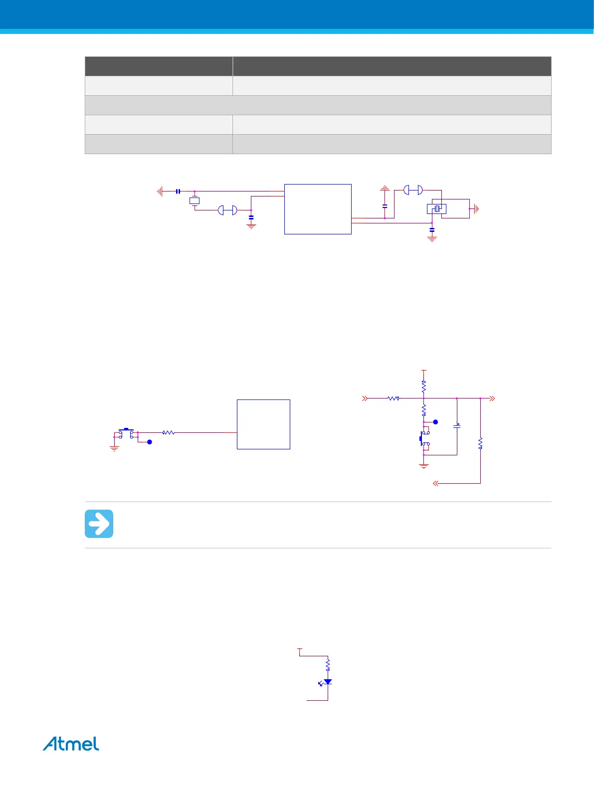
12 MHz External Crystal Connection
PB9 XIN: Main Oscillator Input
PB8 XOUT: Main Oscillator Output
Figure 4-19 SAM E70 Crystals Schematic
SAME70
XIN
XOUT
C302
12pF
C303
12pF
XC301
12MHz
3
21
4
PB8
141
PB9
142
1 2
PA8
PA7
XOUT32
XIN32
PA8
J300
12
C301 18pF
DNP
36
35
XC300
32.768 kHz
DNP
C300
18pF
DNP
PA7
4.4.2. Mechanical Buttons
Two pushbutton switches are available. When a button is pressed, it drives the corresponding I/O line to
GND.
• One board reset button (SW100). When pressed and released, this pushbutton causes a power-on
reset of the whole board.
• One wakeup pushbutton that brings the processor out of Low-power mode (SW300)
Figure 4-20 Mechanical Button Schematic
VCC_3V3
EDBG_TARGET_RESET
TARGET_RESET_SENSE
TARGET_RESET
R110
39R
C104
10nF
R122
0R
TP100
SW100
1
42
3
R107
330R
R106
100K
SAME70
USER BUTTON
WKUP6
PA11
R300
39R
PA11
64
TP300
SW300
1
42
3
Important: There is no pull-up resistor connected to SW300 button. Remember to enable the
internal pull-up in the SAM E70 to use the button.
4.4.3. LEDs
There is one green LED mounted on the SAME70-XPLD. It can be activated by driving the connected I/O
line to a low level.
Figure 4-21 LED Indicators Schematic
USER LED
LED0
PC8
VCC_3V3
R303
330R
D301
Gree
n
Atmel SAME70-XPLD [USER GUIDE]
Atmel-44050A-SAME70-XPLD_User Guide-12/2015
31