Do you have a question about the Atmor Super 900 and is the answer not in the manual?
Locate the ideal installation spot and prepare by drilling four holes and inserting plugs for mounting.
Access the unit's rear by opening the cable entrance, ensuring the side of the cable is accessible.
Mount the unit securely on the wall using four screws, remembering to insert the electric cable beforehand.
Attach the cold water hose to the unit's inlet on the left side, using rubbers and a reinforced hose.
Connect the hot water hose to the outlet, using rubbers and a reinforced hose, then check for leaks.
Wire the electric cable to the unit's terminal block, ensuring correct connections.
Secure the unit's cover with four short screws and then insert the gray bottom cover.
Identify the ideal mounting location and prepare the wall by drilling holes for the unit.
Access the unit's rear cable entry point, ensuring the side of the cable is prepared for connection.
Select the best installation site and use the template to mark and drill four holes for mounting.
Mount the unit onto the wall using four screws, ensuring the electric cable is inserted prior to securing.
Attach the cold water supply hose to the unit's left-side inlet using rubbers and a reinforced hose.
Connect the hot water hose to the outlet, verify for leaks after turning on water supply.
Connect the electrical supply cable to the designated terminal block within the unit.
Reattach the unit's main cover and secure it using four short screws.
Install the gray cover onto the bottom of the unit to complete the housing.
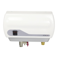
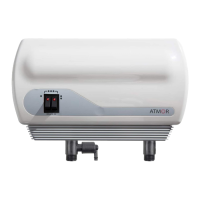
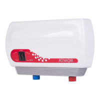
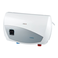
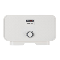
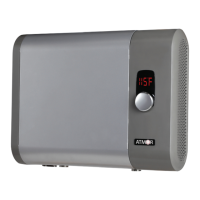
View of the fully assembled InLine 3.5kW and 5.0kW models.
The Atmor Super 900 InLine model is a compact, on-demand hot water heater designed for point-of-use applications, providing instant hot water without the need for a storage tank. This manual outlines the assembly and installation steps for various power ratings, including 3.5kW, 5.0kW, and 7.0kW models.
The primary function of the Atmor Super 900 is to deliver hot water on demand, eliminating the waiting time associated with traditional water heaters and reducing energy consumption by heating water only when needed. It is designed for installation directly at the point of use, such as under a sink or near a shower, making it suitable for various domestic and light commercial applications. The unit heats water as it flows through, ensuring a continuous supply of hot water for tasks like hand washing, dishwashing, or showering, depending on the model's power output.
While specific technical specifications like voltage, current, and flow rates are not explicitly detailed in the provided pages, the manual indicates different power ratings:
The unit is designed for wall mounting, as indicated by the drilling and hanging steps. It connects directly to the cold water supply (inlet) and delivers hot water through an outlet connection. Electrical connections are made to a terminal block within the unit, suggesting a direct wired connection to the electrical supply. The design emphasizes a compact form factor, allowing for discreet installation.
The Atmor Super 900 is characterized by its simplicity of use and immediate hot water availability.
The manual primarily focuses on installation, but some aspects hint at maintenance considerations:
The installation process is detailed in a step-by-step manner, starting from finding an optimal location, drilling holes, mounting the unit, connecting water hoses (inlet and outlet), making electrical connections, and finally closing the unit. The manual stresses the importance of ensuring no leaks before proceeding with electrical connections, highlighting a crucial safety and reliability aspect. The "InLine model" designation suggests it is designed to be integrated directly into the water line, often concealed, for a clean and unobtrusive appearance.
| Brand | Atmor |
|---|---|
| Model | Super 900 |
| Category | Water Heater |
| Language | English |