14
Fig. 9
oillevel
~1 cm
Operate the devices ONLY with the machine ON!
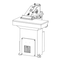
a) Thehandwheellocatedontherightsideofthearmisusedtoadjusttheturningarmstroke.Byturningit clockwise,as indicatedby thearrow
in Fig. 10, the arm moves downward; counter clockwise, the arm moves upward.
RESIDUAL RISK:
Every time you adjust the handwheel, be sure that no strange object (apart from the cutting- die and the material to be cut) is between
the cutting table and the arm. Bear in mind that this handwheel, by mechanically acting on the hydraulic distributor, can cause the
machine to exert its maximum pressure.
Fig. 10
b) Thearmcanbemovedbothtotheleftandtotheright(withatotalrotation of180° about)by meansof thetwo handles.On theright onethere
is the 2--hand control push--button (Fig. 11).
Fig. 11
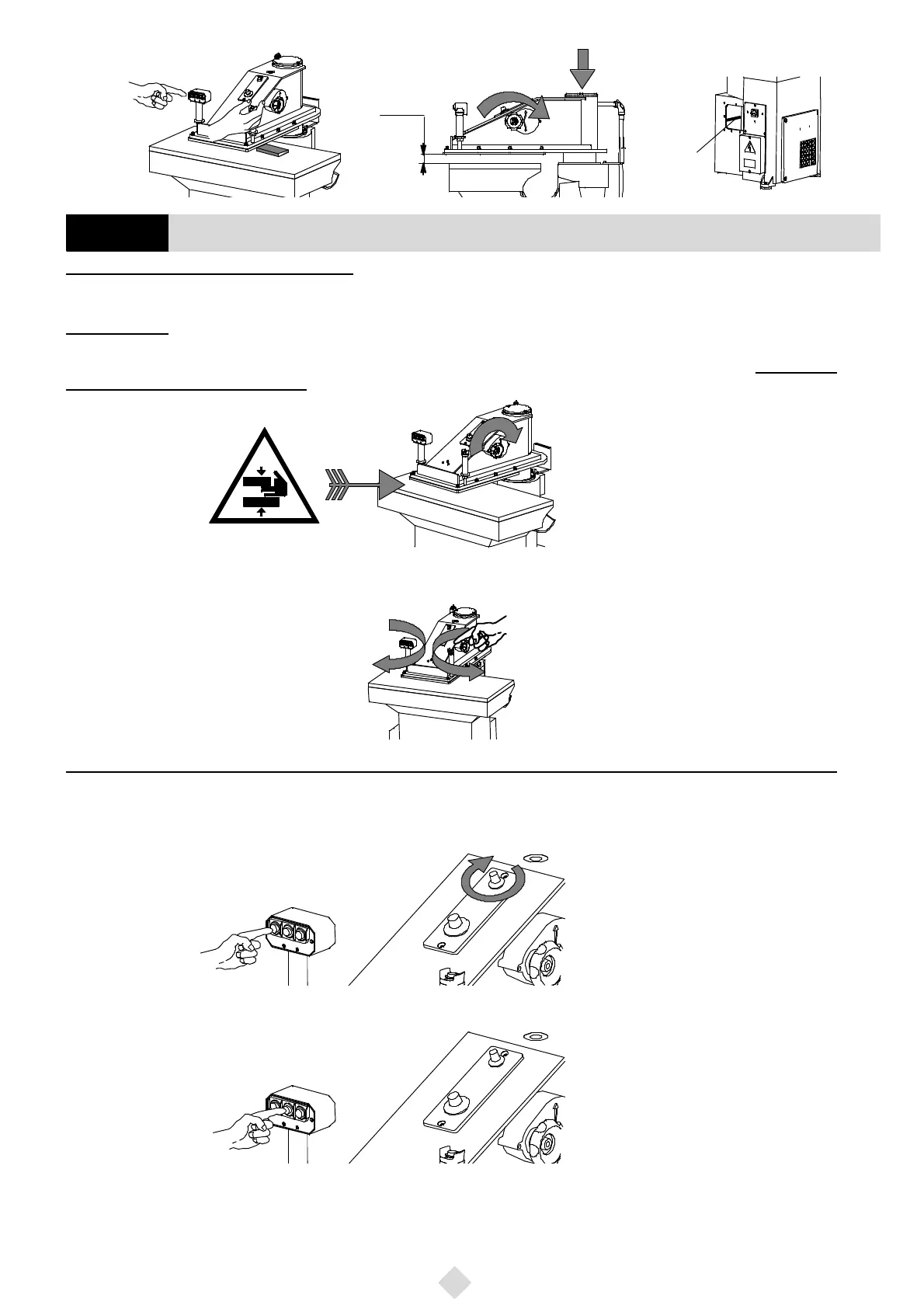
Machine equipped with three--pushbutton cutting power selector and two potentiometers (S100 Series)
c) Onthelefthandlethereisapush--buttonbox withthreepush--buttons:theNo.1,theNo.2andtheNo.3;theseactaspowerselectorsandthe
operatorhasnottoadjustthepowereachtimehechangesthecutting--diesize.Thepush--buttonno.1(Fig. 12),ontheleft,isusedtocutsoftma-
terialsbymeansoftoolswithasmalllineardevelopment.ItispossibletograduallyincreaseitsvaluebymeansofthepotentiometershowninFig. 12
till nearly reaching the power of push--button no. 2.
Fig. 12
d) The pushbutton No.2 (Fig. 13), in the centre, is used to cut semi--hard materials by means of tools with a medium linear development.
Fig. 13
132 Function of the machine control devices
GB