How to connect it: Strip back approximately ½” of the insulation from the Pink w/ gray PCM
power wire and solder the red Co-Pilot wire to the 12 V power wire. Protect this connection.
-Black Wire- GND Ground - PIN #9
Reason for use: The black wire supply’s ground to the Co-Pilot so the Co-Pilot can turn on and
function. NOT OPTIONAL
Where to connect it: On the C2 connector of the PCM which is located on the driver’s side of
the engine block. The ground (black) wire is on the connector that is closer to the firewall in
pin 50.
.
How to connect it: Strip back approximately ½” of the insulation from the black PCM wire and
solder the Co-Pilot’s black wire to the PCM black wire. Protect this connection.
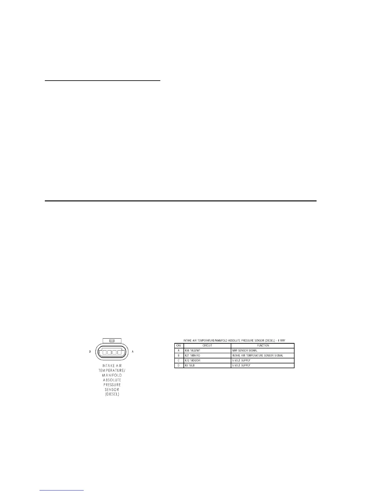
-Orange Wire- Manifold Absolute Pressure (MAP) Sensor - PIN #4 (* OPTIONAL *)
Reasons for use: This function prevents the Torque converter for locking up until 10-13 Psi of
boost has been made. This allows to turbo to begin to spool before the torque converter locks up.
Where to connect it: At the MAP sensor connector located on the driver’s side of the engine,
next to the valve cover, and just over halfway back on the engine. The connector has four wires;
tap the light blue/white wire, which is in the first (“A”) terminal.
How to connect it: Strip back approximately ½” of the insulation from the light blue wire and
solder the Co-Pilot’s orange wire to the light blue/white wire. Protect this connection.
Tips: If the vehicle has had any aftermarket power modules installed, be sure to tap the MAP
sensor wire before any taps from these power modules, i.e. place the Co-Pilot’s tap closest to the
sensor. Do your best to shield this connection from the elements.