Serviceanleitung_US2000V5_EN_V0.0.docx
2.5.2. Mounting the new sonotrode
1. Slide the plastic bushing on the new sonotrode (Note: the hole for the positioning screw is not in the center of
the bushing; the short side has to face the top of the sonotrode).
2. Slide the new sonotrode carefully back into the support until the hole of the sonotrode top bushing is aligned
with the thread of the sonotrode support.
3. Tighten the positioning screw of the top bushing.
4. Hold the sonotrode slide vertical and slowly loosen the positioning screw until the sonotrode drops by its own
weight.
5. Now tighten the lock nut of the positioning screw.
6. Slide the sonotrode all the way up and line up the holes of the sonotrode with the threads in the collar.
7. Thighten all three screws on the collar and make sure that there is an even gap between the sonotrode and
the sonotrode-collar.
8. Tighten the three lock-nuts.
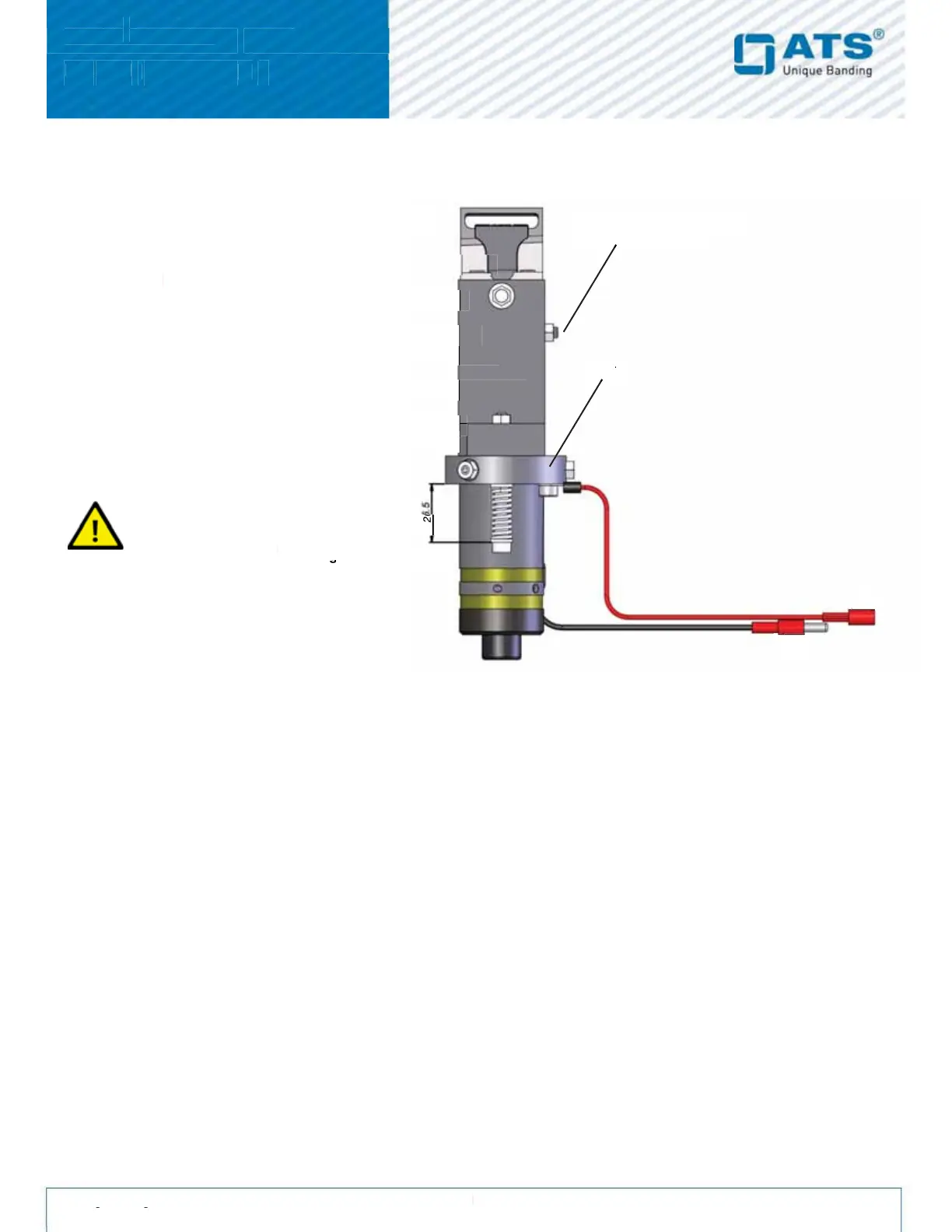
9. Add a new cable tie on both sonotrode wires around the bottom of the sonotrode.
10. Before mounting the sonotrode slide, check the pressure on both sonotrode springs (Setting between collar
and the beginning of the screw should be set to 26.5 mm).
2.5.3. Adjusting the generator
New and repaired sets from ATS are adjusted. Use this instruction in case of welding problems only, if the setting
of a higher welding time does not increase the welding quality.
Remove the sonotrode slide from the unit
Loosen all three locknuts on the collar
Cut the cable tie off the sonotrode.
Remove the black set screw from the top
Carefully pull sonotrode down and out of the
Check the red sonotrode wire for any
damages and replace it if necessary.
screw at the bottom of the
generate high voltage if not
 Loading...