Serviceanleitung_US2000V5_EN_V0.0.docx
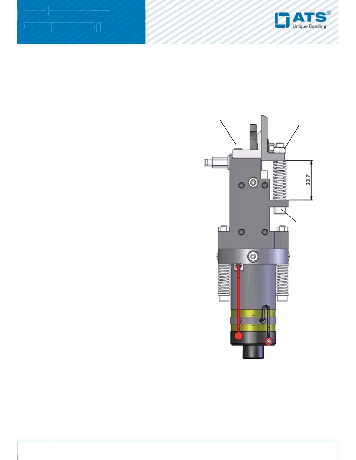
2.6. Cutter
The cutter cuts the band after the welding. The clamp holds the band tight after it has been fed around the arch.
Hint: Cutter, clamping brackets, springs etc. are only available as a set and cannot be ordered individually.
2.6.1. Replacing the cutter
1. Remove the lock-nuts off the setscrews on the clamp.
2. Slowly remove the two fixing screws from the clamp
holder. Caution: Springs are tensioned.
3. Remove both springs from the cutter.
4. Always replace both springs, bolts and locknuts
(delivered with the new cutter).
To mount the new cutter, follow the same procedure
but in reverse order:
1. Adjust the measurement between the clamp and the
Sonotrode holder to exactly 3 mm. This enables
thecorrect pressure against the anvil. It also adjusts
theangle, of how the band enters the arch.
2.6.2. Maintenance of the cutter
The cutter should be lubricated frequently (see monthly
maintenance). If the sonotrode slide is out of the unit, the cutter
should be lubricated with new grease:
1. Remove both screws on the cutter.
2. Turn the cutter on the clamp, until you can see the groove
in the clamps.
3. Check the edge of the cutter and replace it if necessary.
4. Clean all dirt off the grooves of the clamp.
5. Fill the grooves with new grease.
6. Tighten both screws on the cutter.
7. The spring washers should be adjusted so that the two
blades slide against each other smoothly with some
resistanc. The spring washers should be cupped rathar
than flat.
 Loading...