EasyManua.ls Logo

Audio Technica AT-ONE ATW-R1 - User Manual

Audio Technica AT-ONE ATW-R1
10 pages
Print Icon
To Next Page IconTo Next Page
Loading...
AT-ONE Wireless Systems
User Manual
UHF Wireless Systems
RF AF
UP
DOWN
ATW-R1
ATW-R1
Receiver
ATW-T1
Body-Pack Transmitter
ATW-T3
Handheld Transmitter
Question and Answer IconNeed help?

Do you have a question about the Audio Technica AT-ONE ATW-R1 and is the answer not in the manual?

Overview

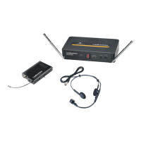
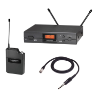
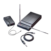
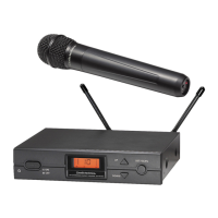
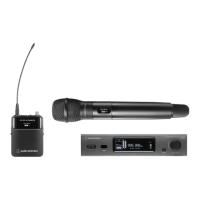
The Audio-Technica AT-ONE Wireless System is a UHF wireless microphone system designed for various audio applications. It comprises a receiver (ATW-R1), a body-pack transmitter (ATW-T1), and a handheld transmitter (ATW-T3).

Function Description:

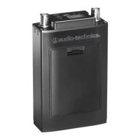
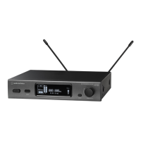
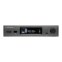
The ATW-R1 receiver is the central unit, responsible for receiving audio signals from the transmitters. It features antenna switching diversity for improved signal reliability. The ATW-T1 body-pack transmitter is designed for use with lavalier or headworn microphones, while the ATW-T3 handheld transmitter is a standalone microphone. Both transmitters convert audio input into a UHF radio frequency signal, which is then sent to the receiver.

Important Technical Specifications:

  • Overall System:

    • Frequency Range: DE3: 482-492 MHz, 495-512 MHz; HH2: 824-831 MHz, 863-865 MHz.
    • Modulation Mode: FM.
    • Number of Frequencies: 2 x 4 frequencies.
    • Operating Range: 60 m, typical.
    • Frequency Response: 60 Hz - 16 kHz.
    • Frequency Stability: +/- 0.005%, phase lock loop frequency control.
  • Receiver (ATW-R1):

    • Receiver System: Antenna switching diversity.
    • Image Rejection: 55 dB minimum.
    • Dynamic Range: HH: 108 dB; BP: 103 dB (@ max deviation).
    • Sensitivity: 10 dBμV (S/N 60 dB @ 20 kHz deviation).
    • Total Harmonic Distortion: <1% - 20 kHz deviation @ 1 kHz.
    • Level Control: Mic/Line (0/-20 dB).
    • Antenna Input: BNC type, 50 ohms - BIAS voltage 12 V DC 100 mA each.
    • Audio Output: Unbalanced -2 dBV, Balanced +4 dBV.
    • Output Connectors: Unbalanced: 1/4" (6.3 mm) mono jack; Balanced: XLRM-type.
    • Dimensions: 200 mm (W) x 42 mm (H) x 122 mm (D).
    • Weight: 418 g without accessories.
    • Accessories Included: AC Adapter, Antennas, Rack-mount adapter, Protective carrying case.
    • Optional System Accessory: AT8677 Dual rack mount kit.
  • Body-Pack Transmitter (ATW-T1):

    • RF Output Power: 10 mW.
    • Spurious Emissions: Following federal and national regulations.
    • Input Connections: Pin 1: GND, Pin 2: INST, Pin 3: Mic, Pin 4: DC Bias + 10 V.
    • Batteries (not included): Two 1.5 V AA alkaline.
    • Battery Life: 10 hours - depending on battery type and use pattern.
    • Dimensions: 66 mm (W) x 98 mm (H) x 22 mm (D).
    • Weight: 71 g without batteries.
  • Handheld Transmitter (ATW-T3):

    • RF Output Power: 10 mW.
    • Spurious Emissions: Following federal and national regulations.
    • Microphone Element: Cardioid condenser.
    • Batteries (not included): Two 1.5 V AA alkaline.
    • Battery Life: 10 hours - depending on battery type and use pattern.
    • Dimensions: 268 mm (long), 52 mm (diameter).
    • Weight: 277 g without batteries.
    • Accessories Included: Stand clamp.

Usage Features:

  • Receiver (ATW-R1):

    • Front Panel Controls: Includes detachable UHF antennas with BNC connectors, a power button (press and hold to power on/off), RF and AF red LEDs to display signal reception status, a channel ID display, and UP/DOWN channel buttons for selecting frequencies. To change a channel, press and hold until the ID blinks, then tap to select, and release to set.
    • Rear Panel Controls: Features BNC receptacles for antennas, balanced XLR audio output, unbalanced 1/4" output, a Mic/Line switch to adjust audio output (-20 dB for mic level, 0 dB for line-level), an SQ (Squelch) knob to adjust the squelch level (counter-clockwise for maximum range, clockwise to block interference), a DC IN connector for the AC adapter, and a cable strain relief.
    • System Setup: The receiver should be placed at least 1 m above the ground and 1 m away from walls or metal surfaces to minimize interference. The transmitter should be at least 3 m from the receiver. Antennas should be kept away from RF interference sources.
    • Connecting the Receiver: Plug the supplied DC 12V 500 mA power supply into the DC IN connector. Connect the receiver output to an audio mixer or amplifier using a 3-pin XLR or 1/4" connector. Avoid using balanced and unbalanced outputs simultaneously to prevent signal loss or increased noise. Adjust the Mic/Line switch to 0 dB (line-level) or -20 dB (mic level) as needed; the factory setting is 0 dB.
  • Transmitters (ATW-T1 Body-Pack & ATW-T3 Handheld):

    • Power/Mute Button: Press and hold to power on/off.
    • Power/Mute/Battery Status LED: Indicates power, mute, and battery level status.
      • Green: Ready
      • Red: Muted
      • Green Flashing: On, low battery
      • Red Flashing: Muted, low battery
      • No Light: No power
    • Battery Compartment: Both transmitters require two AA batteries. Ensure correct polarity when inserting. For the handheld mic, unscrew the bottom to access the compartment.
    • Channel Selector: Used to change the channel setting (e.g., from 11-14 or 21-24).
    • Transmitter Gain Selector (ATW-T1 only): Rotary control to adjust the sensitivity of the transmitter's audio input.
    • Pad Switch (ATW-T1 only): Attenuates the signal by an additional 10 dB.
    • Input Connector (ATW-T1 only): Locking 4-pin connector for Audio-Technica cW-style lavalier and headworn microphones or cables.
    • Power On/Off: Press and hold the power button for 4 seconds to turn on. If the LED flashes (red or green) after 4 seconds, the battery is low.
    • Frequency Adjustment: Use a small standard screwdriver or similar object to adjust the transmitter's frequency to match the receiver's channel. '1' corresponds to the first frequency in Group 1, '2' to the first frequency in Group 2. Turn off the transmitter when switching frequency to avoid pops.
    • Audio Input Level: Use the 0 dB/-10 dB switch to adjust the audio input level.

Maintenance Features:

  • General Maintenance:

    • Electrical shock can result from removal of the receiver cover. Refer servicing to qualified service personnel.
    • The circuits inside the receiver and transmitter have been precisely adjusted for optimum performance and compliance with federal regulations. Do not attempt to open the receiver or transmitter. To do so will void the warranty and may cause improper operation.
    • Notice to individuals with implanted cardiac pacemakers or AICD devices: Any source of RF (Radio Frequency) energy may interfere with normal operation of implanted devices. All microphones have low-power transmitters (less than 0.05 watts output) which are unlikely to cause difficulty, especially if they are at least a few inches away.
    • However, since a body-pack transmitter typically is placed against the body, it is suggested to clamp it to a belt rather than a shirt pocket where it may be immediately adjacent to the medical device.
    • Note also that any medical device disruption will cease when the RF transmitting source is turned off. Please contact your physician or medical device provider if you have any questions, or experience any problems with the use of this or any other RF equipment.
    • Please note that wireless frequencies are shared with other radio services.
    • If you need assistance with operation or frequency selection, please contact your dealer or Audio-Technica. Extensive wireless information is also available at www.audio-technica.com.
  • Troubleshooting:

    • No Sound: Check the power supply of the transmitter and receiver. Ensure that the transmitter and receiver are tuned to the same frequency. Check that the receiver is correctly connected to the mixer or amplifier. Check whether the transmitter is too far from the receiver or the Squelch control is set too high. Check for obstructions between the transmitter and receiver.
    • Interference: Check the location for RF interference. When using two or more units simultaneously, make sure the chosen frequencies do not interfere with each other. Check whether the interference is coming from other wireless microphones, LTE, etc. When using two or more sets, keep the distance between the receiver and the transmitter greater than 3 m and the distance between the two transmitters greater than 1 m to avoid cross-talk interference.
    • Distortion: Check whether the receiver volume level is set too high or too low. Check whether the distortion is coming from other wireless microphones, TV, radio, etc. being used in the area.
    • Rackmount Setup: To mount the receiver in a 19" standard rack using the included rack kit, attach the L-shaped brackets to the opposite end of the unit and mount in the rack unit. To connect two receivers in a 19" standard rack using the optional AT8677 rack kit (sold separately), attach the short L-shaped brackets to the opposite end of each unit, and connect the units together using two metal connecting plates.
  • Battery Safety:

    • To prevent fire or shock hazard, do not expose this appliance to rain or moisture.
    • To prevent fire, do not cover the ventilation of the apparatus with newspaper, tablecloths, etc.
    • Do not expose this apparatus to drips or splashes.
    • Do not place any objects filled with liquids, such as vases, on the apparatus.
    • Do not install this apparatus in a confined space such as a bookcase or similar unit.
    • The apparatus should be located close enough to the AC outlet so that you can easily grasp the AC adapter at any time. In case of emergency, disconnect the AC adapter quickly.
    • Danger of explosion if battery is incorrectly replaced. Replace only with the same or equivalent type.
    • If the transmitter is not in use for an extended period, remove the batteries to avoid damage.
    • Do not dispose of used batteries with domestic rubbish. Be sure to dispose of batteries in accordance with your local waste disposal rules.
    • When disposing of the equipment, remove the batteries, separate the case, circuit boards, and cables, and dispose of all components in accordance with local waste disposal rules.

Audio Technica AT-ONE ATW-R1 Specifications

General IconGeneral
BrandAudio Technica
ModelAT-ONE ATW-R1
CategoryMicrophone system
LanguageEnglish

Related product manuals