Version 5.6 5 November 2008
Installation Manual Contents
List of Figures
Figure 1-1: Flowchart for Installing the Device ........................................................................................ 9
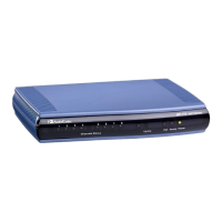
Figure 2-1: MP-11x (e.g., MP-118) Front Panel .................................................................................... 10
Figure 2-2: MP-11x (e.g., MP-118) Rear Panel Connectors ................................................................. 10
Figure 2-3: View of MP-11x Underside .................................................................................................. 12
Figure 2-4: AudioCodes 19-inch Rack Shelf for MP-11x ....................................................................... 13
Figure 2-5: MP-11x Rack Mount ............................................................................................................ 13
Figure 2-6: RJ-45 Connector Pinouts .................................................................................................... 14
Figure 2-7: RJ-11 Phone Connector Pinouts ......................................................................................... 15
Figure 2-8: RJ-11 Lifeline Splitter Connector Pinouts ........................................................................... 16
Figure 2-9: PS/2 Connector Pinouts ...................................................................................................... 17
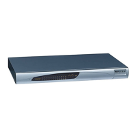
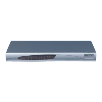
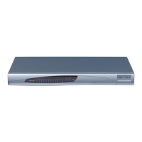
Figure 2-10: MP-124 Front Panel .......................................................................................................... 18
Figure 2-11: MP-124 Rear Panel - AC Power Model ............................................................................ 19
Figure 2-12: MP-124 Rear Panel - DC Power Model ............................................................................ 19
Figure 2-13: MP-124 Desktop Mounting ................................................................................................ 20
Figure 2-14: MP-124 with Brackets for Rack Installation ....................................................................... 21
Figure 2-15: MP-124 Wiring Using Earthing Screw on Rear Panel ....................................................... 23
Figure 2-16: MP-124 Wiring Without Using Earthing Screw.................................................................. 24
Figure 2-17: RJ-45 Connector Pinouts .................................................................................................. 24
Figure 2-18: 50-pin Telco Connector (MP-124/FXS only) ..................................................................... 25
Figure 2-19: MP-124 in a 19-inch Rack with MDF Adaptor ................................................................... 26
Figure 2-20: MP-124 RS-232 Connector Pinouts .................................................................................. 27
Figure 2-21: Wired DC Power Terminal Block Connected to MP-124 .................................................. 28
Figure 3-1: Enter Network Password Screen ........................................................................................ 30
Figure 3-2: BootP Client Configuration Screen ..................................................................................... 32
Figure 3-3: Assigning Phone Numbers in the Endpoint Phone Number Table Page ............................ 37
Figure 3-4: Defining Tel-to-IP Call Routing in the Tel to IP Routing Page ............................................ 37
Figure 3-5: Connecting Two Devices ..................................................................................................... 38
Figure 3-6: Maintenance Actions Page.................................................................................................. 39
Figure 3-7: Configuration File Page ....................................................................................................... 40
Figure 3-8: Web User Accounts Page (for Users with 'Security Administrator' Privileges) ................... 41
Figure 3-9: Start Software Upgrade Wizard Screen .............................................................................. 43
Figure 3-10: Load CMP File Wizard Page ............................................................................................. 44
Figure 3-11: CMP Successfully Loaded Wizard Page ........................................................................... 45
Figure 3-12: End Process Wizard Page ................................................................................................ 46
Figure 3-13: Load Auxiliary Files Page .................................................................................................. 48
Figure 4-1: Current Alarms in Active Alarms Page ................................................................................ 50
Figure 4-2: MP-11x Home Page ............................................................................................................ 51
Figure 4-3: MP-124 Home Page ............................................................................................................ 51

 Loading...