1) The connection board for overvoltage is not suitable for
component redundancy (page 50).
Actuator controls AUMATIC AC 01.1 / ACExC 01.1
Profibus DP Operation instructions
14
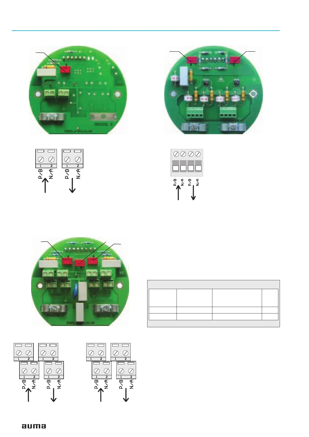
Figure C-2: Connection board (for overvoltage protection)
1)
S1
Bus termination
Channel 1
S2
Bus termination
Channel 2
Figure C-1: Connection board (standard)
S1
Bus termination
Channel 1
X1
1234
Figure C-4: Connection for overvoltage protection
1)
from previous / to next
Profibus DP device
Channel 1
X1 X2
Figure C-3: Connection (standard)
from previous / to next
Profibus DP device
Channel 1
Figure C-5: Connection board (for component redundancy)
S2
Bus termination
Channel 2
S3
S1
Bus termination
Channel 1
Profibus
cable
AUMA
labelling at
connection
SUB-D 9 connector
(for other
Profibus devices)
Colour
A N/A 8 green
B P/B 3 red
Table 4: Assignment of the Profibus cable
X1 X2 X3 X4
Figure C-6: Connection for component redundancy (option)
from previous / to next
Profibus DP device
Channel 1
from previous / to next
Profibus DP device
Channel 2

 Loading...

