7.4 Fitting of the connection
housing
After mains connection:
.
Insert the socket carrier (51.0) into the plug cover (50.0) and fasten it with
screws (51.01).
.
Clean sealing faces at the connection housing and the actuator housing.
.
Check whether O-ring is in good condition.
.
Apply a thin film of non-acidic grease (e.g. Vaseline) to the sealing faces.
.
Replace connection housing (50.0) and fasten bolts (50.01) evenly cross
-
wise.
.
Fasten cable glands with the specified torque to ensure the required enclo
-
sure protection.
7.5 Test run Perform test run. Refer to the operation instructions for the actuator
(multi-turn actuator SA(R) … / part-turn actuator SG ...).
Check limit and torque switching:
Check limit and torque switching, electronic position transmitter RWG or
potentiometer (option) and, where necessary, re-set.
The settings are described in the operation instructions to the actuator
(multi-turn actuator SA(R) … part-turn actuator SG … ).
For actuators with feedback signal (RWG, potentiometer), a reference oper
-
ation has to be performed after the setting has been changed.
Perform reference operation:
.
Run actuator electrically (via the push-buttons OPEN and CLOSE) of the
local controls once to the end position OPEN and once to the end position
CLOSED.
.
If no reference operation is performed after changing the limit switching,
the feedback signal via the bus is not correct. The bus signals the missing
reference operation as warning (see page 31).
7.5.1 Bus connection (standard) For explosion-proof version (type designation: ACExC) see page 15.
For version with FO (fibre optics) refer to separate operation instructions
“AUMATIC AC 01.1 FO connection”.
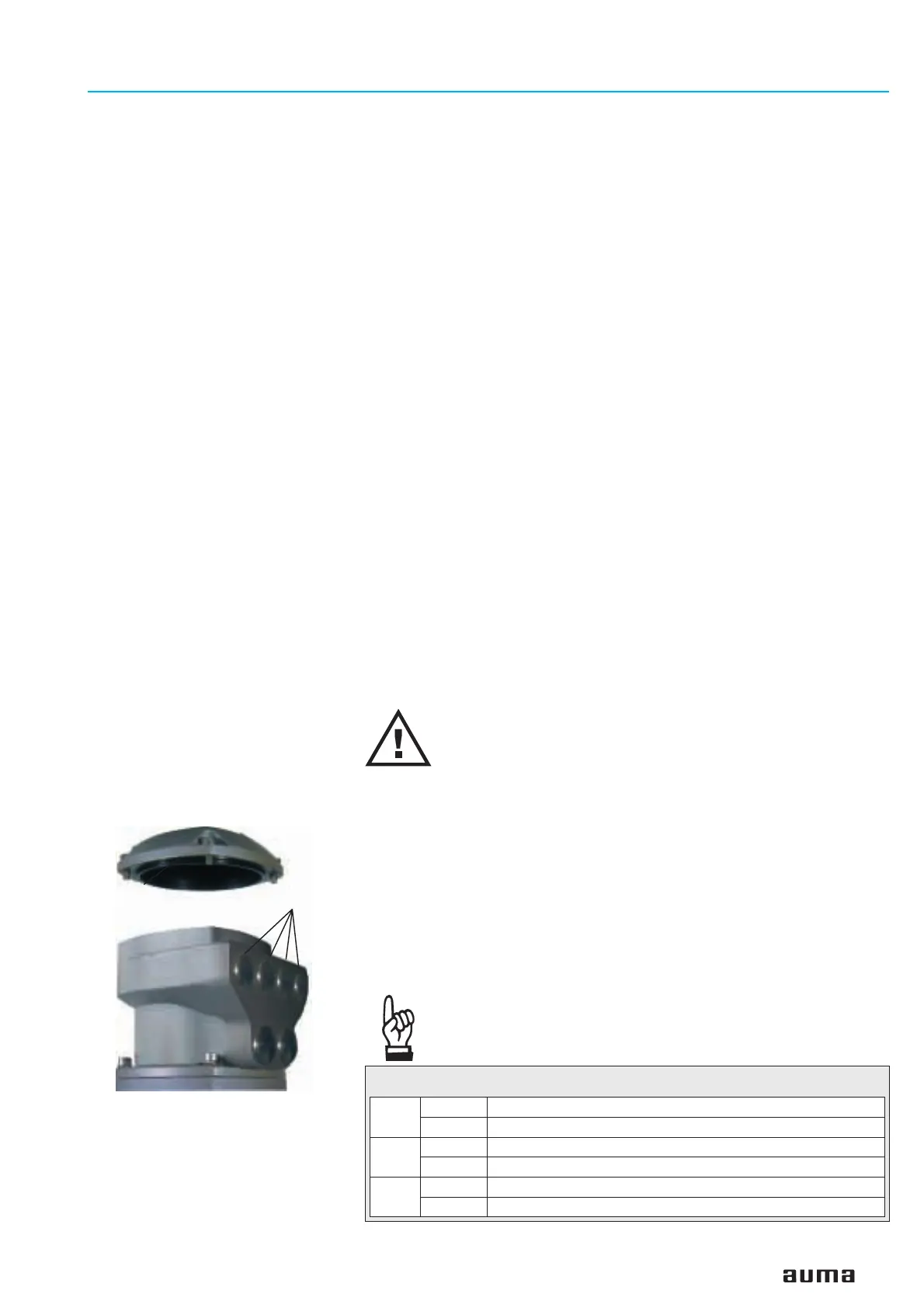
Disconnect power before removing the plug cover.
.
Loosen and remove plug cover (figure B-3). The connection board
(figures C-1, C-2 and C5) is located behind the plug cover.
.
Insert cable glands suitable for bus cables.
(The enclosure protection stated on the name plate is only ensured if suit
-
able cable glands are used).
.
Seal cable entries which are not used with suitable plugs.
.
Connect bus cable. Refer to figures C-1 to C-6.
The termination resistors for channel 1 and channel 2 are switched in via
switches (S1) and (S2). Both switches are supplied in position ‘OFF’. Only
connect the termination resistors (position ’ON’) if the actuator is the final
station in the Profibus segment.
As soon as the termination resistors are switched on, the
connection to the next Profibus DP device is automatically
interrupted to avoid multiple terminations.
Actuator controls AUMATIC AC 01.1 / ACExC 01.1
Operation instructions Profibus DP
13
Figure B-3: AUMATIC bus
connection
Plug cover
Entries for bus
cables
S1
ON Bus termination channel 1 ON
OFF Bus termination channel 1 OFF
S2
ON Bus termination channel 2 ON (option)
OFF Bus termination channel 2 OFF (option)
S3
1SPC one Profibus board
2SPC two Profibus boards (component redundancy, option)
Table 3: Switch positions from S1 – S3

 Loading...

