8. Commissioning with controls
8.1 Introduction When commissioning a Profibus DP network, the devices on the Profibus DP
must be parameterized and configured with the programming software of the
controls (Profibus configurator).
The programming software first reads the GSD file (GeneralStationData) of
the individual actuators. The GSD file contains information about the proper
-
ties of the device which are needed by the master. The GSD file can be
downloaded from our website www.auma.com.
Afterwards, the user can configure and parameterize each device on the
Profibus DP for the programming software of the process control system.
This information is then stored in the controls (DP master) and sent to the
actuators (DP slaves) each time the cyclic communication is started.
The control is executed via the process representation input and output
bytes.
If a configuration with consistent data is chosen, special functional elements
for the control of the Profibus DP slaves must be used with some PLCs.
8.2 Programming The parameterization is partly determined in the Profibus standard, e.g. a bit
for switching bus monitoring on and off (watchdog).
The AUMA Profibus DP controls can additionally receive up to 37 bytes of
‘user parameters’, in which AUMA specific parameters can be set. The
AUMA specific parameters are divided into 34 parameters with 1 byte each
per parameter. The parameters can be changed via the programming soft
-
ware of the controls. New programming software supports the setting of the
parameters via text and menu selection. When using older software the
values of the parameters must be entered using hexadecimal numbers.
The meaning of the individual AUMA specific parameters is explained in
subclause 8.5 .
Note:
AUMATIC actuator controls with the logic software version Z031.922/04-00
and earlier (see diagnosis page D6) have a reduced parameter number. At
www.auma.com, you can find a GSD file with restricted functionalities.
8.3 Configuration of the Profibus DP interface of the AUMATIC
During configuration it is determined how many input and output bytes for
each device are reserved in the memory of controls. Additionally it is deter-
mined if the data are processed consistently or non-consistently.
Only the number of bytes determined in the configuration is
transferred between the DP master and the DP slave.
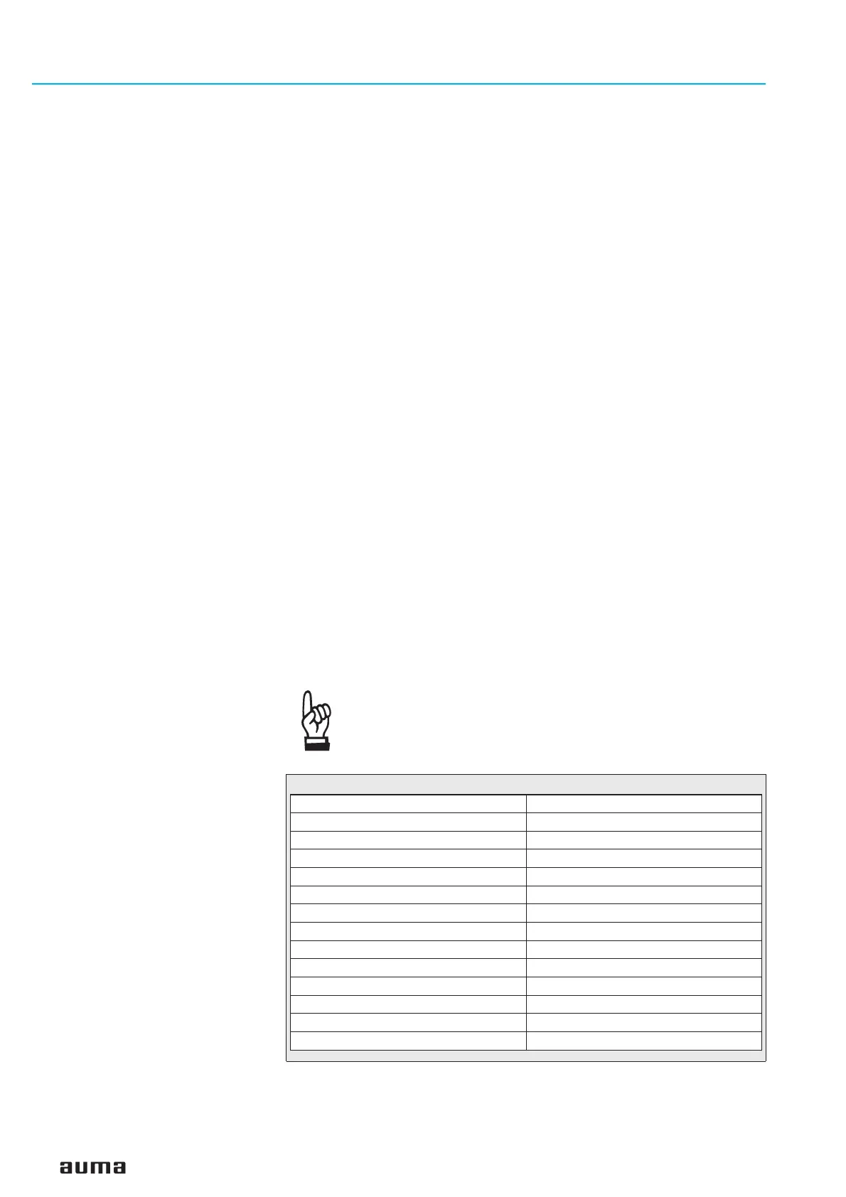
The following configurations are possible with AUMA Profibus DP actuators:
Actuator controls AUMATIC AC 01.1 / ACExC 01.1
Profibus DP Operation instructions
20
Number of input bytes Number of output bytes
11
21
22
44
46
61
62
64
66
84
86
12 4
12 6
Table 7:

 Loading...

