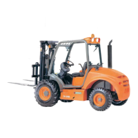
16
CH 200 / CH 250
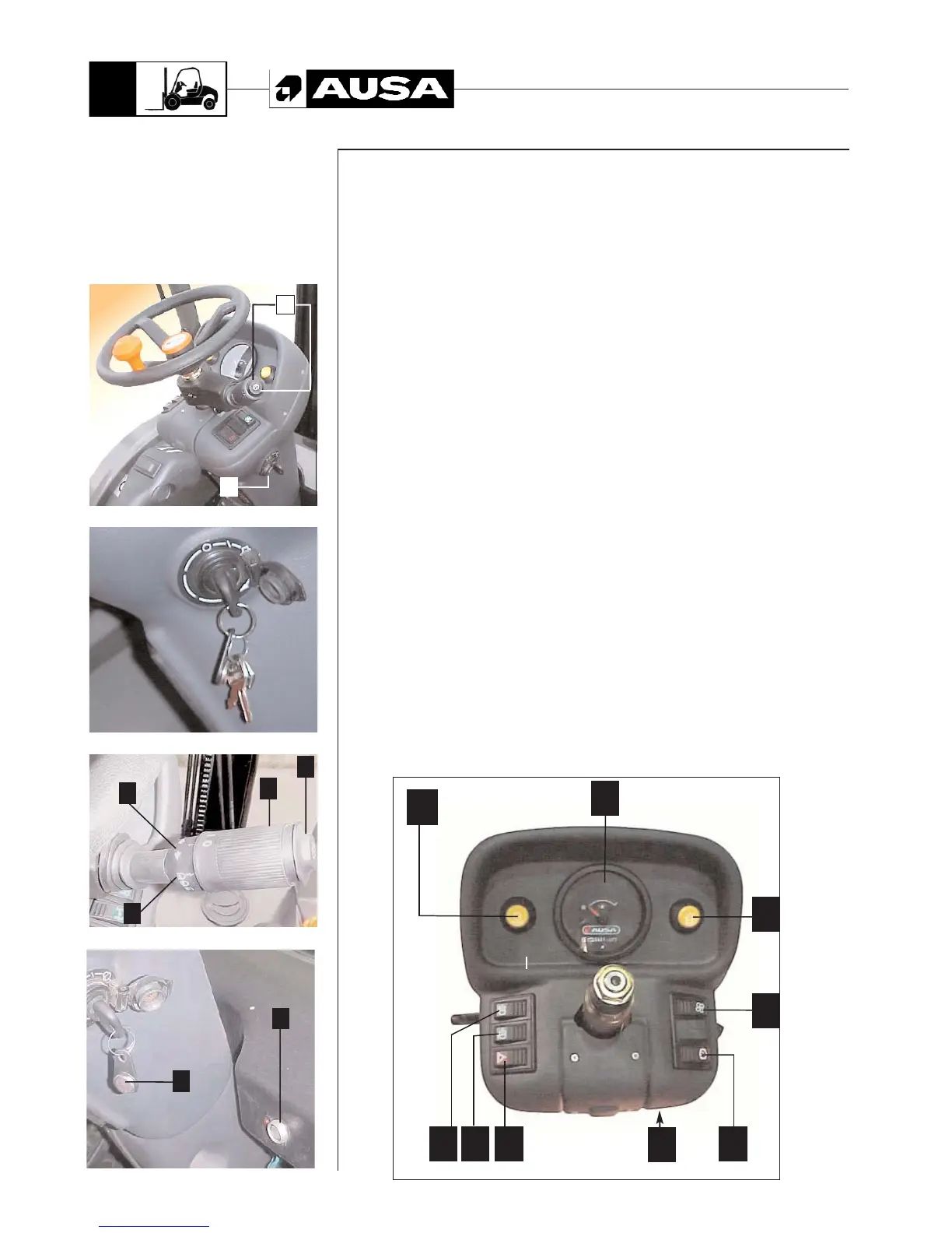
Components
1 - Multifunction Instrument (see next page)
2 - Rotating beacon switch. To switch on, push the button, it will light, to switch off push the
button again.
3 - Parking brake switch. When the parking brake is applied, the button lits.
4 -Lighting switch (version with lighting equipment). This switch has two positions, the first
connect the parking lights and the second connects the low beams.
5 - Working lamp switch (version with lighting equipment). This switch connects the wor-
king lamp if it is assembled.
6 - Hazard warning switch (only in forklift with lights). This switch connects the warning
lights on the four corners of the forklift.
7 - Heating fan switch (version with closed cabin). The heating fan has two speeds which
are regulated by this switch.
8 - Fuse box. The fuse box has places for 11 fuses. See the Electrical Diagram at the rear of this
Manual to identify the number and function of each fuse.
9 - Switch lever for turn signal, high beam, windshield wiper and water pump (version
with lighting equipment or windshield)(fig.3)
9.1 Turn signal switch. Push the lever to the right or to the left according to the side
chosen for turning.
9.2 High beam switch. Push the lever upward to switch on the high beams. When
connected high beam lamp on the dashboard is lit.
9.3 Windshield wiper switch. Turn the lever to switch on the windshield wipers.
9.4 Windshield water pump switch. Push this button at the end of the lever, to
switch on the water pump.
10 - Starter switch. See clause “starting the engine”.
11 - Anti-theft system of security (optional). it is activated or disabled by means of the record
located in the key ring (1) confronting it to the sensor (2). (fig.4)
12 - This pushbutton does not have any function.
(fig. 1)
(fig. 3)
4
1
2
3
10
(fig. 2 - STARTING KEY DETAIL)
9
1
2
(fig. 4)
Instrument
Panel
and controls
(See fig. 2)
1
2
4 5 6 3
8
(fig. 1)
8
12