"'f'!
{I'
THE LAMPS
Dip and Switch Mechanism and How to
Replace Fuses
T
HE head lamps are provided with an electrically operated anti..!azzle
device for operation by the foot switch. When the switch is moved.
to the "dip" position, the near-side headlamp beam is dipped and
turned to the nearside of the road, while at the same time, the offside head-
lamp is switched off, thus causing no discomfort to drivers of approaching
traffic.
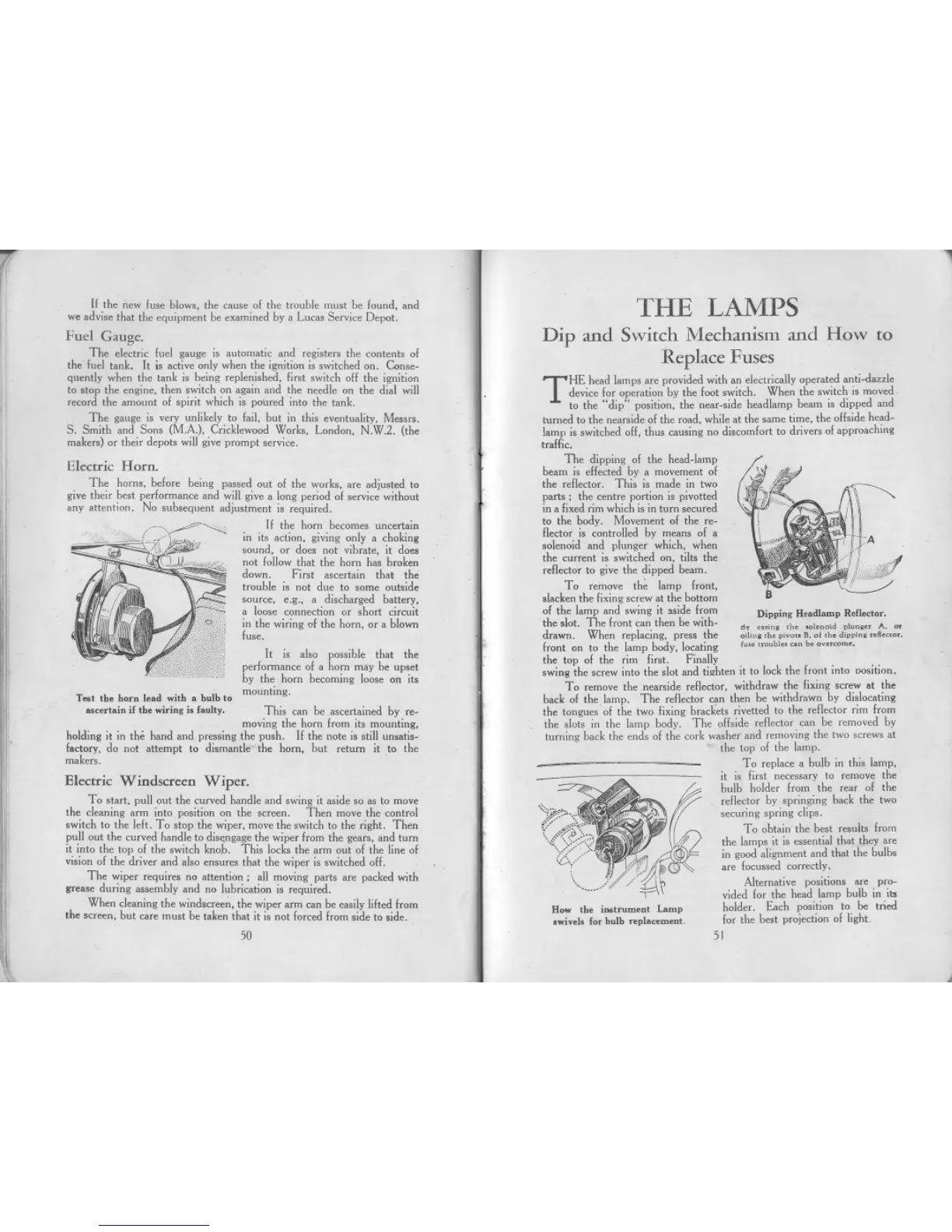
The dipping of the head-lamp
beam is effected by a movement of
the reflector. This is made in two
parts; the centre portion is pivotted
in a fixed rim which is in turn secured
to the body. Movement of the re-
flector is controlled by means of a
solenoid and plunger which, when
the current is switched on, tilts the
reflector to give the dipped beam.
To remove th~ lamp front,
slacken the fixing screw at the hottom
of the lamp and swing it aside from mpping Headlamp Reflector.
the slot. The front can then he wIth- " .
h I
.
d I A
. "' mm, , . m.no. pun,.. . M
drawn. When replacmg, press the o,l;n,,h. pivouB.of,h. d'pp'n, ..awo..
front on to the lamp hody, locating fu.. ,"oubl.".n b. ov",om..
the top of the rim first. Finally
swing the screw into the slot and tighten it to lock the Iront into DOsition.
To remove the nearside rellector, withdraw the lixing screw at the
back of the lamp. The rellector can then be withdrawn by dislocating
the tongues 01 the two lixing hrackets rivetted to the rellector rim from
the slots in the lamp body. The offside rellector can be removed by
turning back the ends 01 the cork washer and removing the two screws at
the top 01 the lamp.
To replace a bulb in this lamp,
it is lirst necessary to remove the
bulb holder Irom the rear 01 the
rellector by springing back the two
securing spring clips.
To obtain the best results lrom
the lamps it is essential that they are
in good alignment and that the bulbs
are locussed correctly.
Alternative positions are pro-
vided lor the head lamp bulb in ihl
holder. Each position to be tried
lor the best projection 01 light.
51
If the new luse blows, the cause 01 the trouble must be found, and
we advise that the equipment be examined by a Lucas Service Depot.
Fuel Gauge.
The electric fuel gauge is automatic and registers the contents 01
the'luel tank. It is active only when the ignition is switched on. Conse-
quently when the tank is being replenished, lirst switch off the ignition
to stop the engine, then switch on again and the needle on the dial will
record the amount 01 spirit which is poured 'into the tank.
The gauge is very unlikely to lail, but in this eventuality, Messrs.
S. Smith and Sons (MA), Cricklewood Works, London, N.W.2. (the
makers) or their depots will give prompt service.
Electric Horn.
The horns, belore being passed out 01 the works, are adjusted to
give their best perlormance and will give a long period 01 service without
any attention. No subsequent adjustment is required.
If the horn becomes uncertain
in its action, giving only a choking
sound, or does not vibrate, it does
not lollow that the horn has broken
down. First ascertain thal the
trouble is not due to some outside
source, e.g., a discharged battery,
a loose connection or short circuit
in the wiring 01 the horn, or a blown
luse.
It is also possible that the
perlormance 01 a horn may be upset
by the horn becoming loose on its
Test the horn lead with a hulh to mounting.
ascertaiu if the wiriug is faulty. This can be .ascertained by re-
. moving the horn lrom its mounting,
holding it in the hand and pressing the push. If the note is still un..tis-
lactory. do not attempt to dismantle the horn, but return it to the
makers.
I
!'
Electric Windscreen Wiper.
To start, pull out the curved handle and swing it aside so as to move
the cleaning arm into position on the screen. Then move the control
switch to the Ielt. To stop the wiper, move the switch to the right. Then
pull out the curved handle to disengage the wiper Irom the gears, and turn
it into the top 01 the switch knob. This locks the arm out 01 the line 01
vision 01 the driver and also ensures that the wiper is switched off.
The wiper requires no attention; all moving parts are packed with
grease during assembly and no lubrication is required.
When cleaning the windscree~, the wiper arm can he easily lifted Irom
the screen, but care must be taken that it is not lorced Irom side to side.
11
~
';{i~~~;,:;:~:
(../'"
How the ;..trument Lamp
swivels for hulh replacement.
50
,
A
.
 Loading...