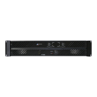
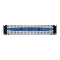
TEST PROCEDURE MODEL - AMIS 250 (US)
1. Perform physical inspection (Visual Inspection stage).
1.1 Check:
• All screws for tightness (esp. bridge rectifier and transistor bolts),
• Earth connection for good contact (XLR GND to AC earth),
• All wiring points for good contacts (soldering and crimping)
PRETESTING
PRE TESTING SETUP REQUIREMENT
a. Oscilloscope.
b. Variac
c. Multimeter.
d. Load [4Ω]
e. Signal generator
2. Set up amplifier for test :
2.1 Check :
• AC fuses (8A), 20mm
• DC fuses (10A), 20mm
•
2.2 Connect amplifier to :
• Variac (0 VAC),
• Signal generator (mic1, no signal),
• Resistive load ( 4Ω on 4Ω terminal ).
• Connect 24V DC supply externally for the relay on amplifier PCB. (Optional test for 24V DC
operation)
2.3 Reset controls :
• Volume controls to minimum,
• Bass/treble control to center,
• R33 & R34 (Bias adjust pots) Amplifier PCB fully anticlockwise.
3 Power up :
3.1 Turn on the power switch and adjust the variac voltage to 115VAC . Watch current meter for
excess current draw. Current should not exceed 0.5A.
3.2 Check DC power supply at the fuses, the measurement should be approximately. 40V (±1.5V)
3.3 Check DC voltage on the mixer board, the measurement should be approximately. 15V (± 0.5V).
3.4 Check 1/2 VCC on mixer board, the measurement should be 8VDC (± 0.5).
3.5 Measure the DC voltages on the IC’s of the mixer & input PCB's, Pin 8, 15V (+
5%), Pin 4 0V
(+100mV),
Pin l, 8V (± 5%) but on power it should be P8 18V (± 5%) other remain same.
3.6 Put a multimeter across R47, the meter should read 0.3 mV (± 5%). Slowly adjust the preset
R 33 so that you measure 2.5mVin addition to the base reading
3.7 Repeat 3.7 for R55 adjusting preset R34.
 Loading...