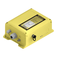
EasyManuals Logo

AUTEC DCRM24 User Manual

AUTEC DCRM24
8 pages
To Next Page IconTo Next Page
To Previous Page IconTo Previous Page
Page #2 background imageLoading...
Page #2 background image
2
LIRMGE00-01
Description
AUTEC - Air series
1 Description
A
B
F
G
E
C
D
H
J
K
L
N
P
S
T
Q
R
U
V
M
M
M
A Identi󰘰cation plate
B Technical data plate
C ENABLE LED
D POWER LED
E
Connector for cable control
(optional)
F
BNC connector for external
antenna kit (optional)
G Cable gland or plug
H Digital inputs
J
Electronic module and address
key
K STOP contacts protection fuses
L DIP switches
M Internal light signals
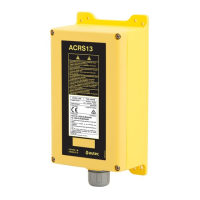
N
Connector for the cable
control's wiring
P
SAFETY contacts protection
fuse
Q Outputs of relay commands
R SAFETY output
S STOP outputs
T Connectors for power supply
U Power supply protection fuse
V
Outputs of solid state
commands

Questions and Answers:

Question and Answer IconNeed help?

Do you have a question about the AUTEC DCRM24 and is the answer not in the manual?

AUTEC DCRM24 Specifications

General IconGeneral
BrandAUTEC
ModelDCRM24
CategoryControl Unit
LanguageEnglish

Related product manuals