AUTEC - Air series
Warnings for installation 5
LIRMGE00-01
4.3 Plates on DCRM24 unit in a Multi Units or Multi Receiver radio remote
control
Plate Position Content
radio remote control
identication plate
On the cover of each
receiving unit.
Radio remote control serial number
(MULTI S/N), bar code and
manufacturing year.
receiving unit
identication plate
On the cover of each
receiving unit.
The serial number of the receiving unit
(S/N) and a bar code.
technical data plate
On the cover of each
receiving unit.
MODEL, TYPE and main receiving unit
technical data, marking and possible
radio remote control marks.
5 Warnings for installation
5.1 Wiring
The following warnings complete and/or replace the corresponding information in the
paragraph about part A.
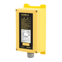
Outputs of solid state commands shall never be connected to a power supply
positive or negative pole. Such connection could damage the outputs.
A voltage in the range 12 to 24 V must always be applied to the power
supply input of the solid state commands.
Common wire related to diodes of solid state commands must be connected
with the common of all the machine's recovery diodes. If that is not possible,
connect it to the receiving unit's power supply negative.