8
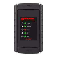
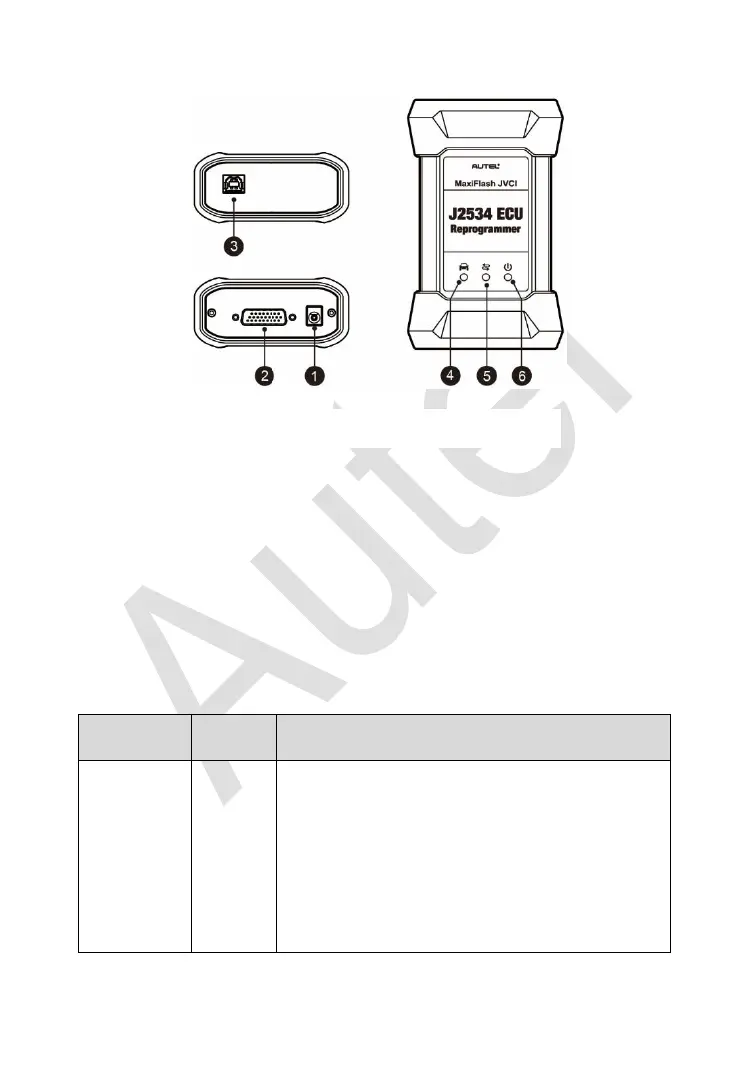
Functional Description
1. Power Port – connects the device and the power source with the adapter.
2. Vehicle Connector – connects the device to the vehicle’s DLC via a
standard high density DB-26 MVCI – OBDII cable.
3. USB Port
4. Vehicle LED
5. Connection LED
6. Power LED
Table 2-2 LED Status
Flashes green when communicating with the
vehicle’s system.
Note: Do not disconnect while this status LED
is on! If you interrupt the flash reprogramming
procedure while the vehicle’s ECU is blank or
only partially programmed, the module may be
unrecoverable.
Figure 2-4 MaxiFlash Views
 Loading...