Revised 7/30/02 • S6104 9 © 2002 Automated Logic Corporation
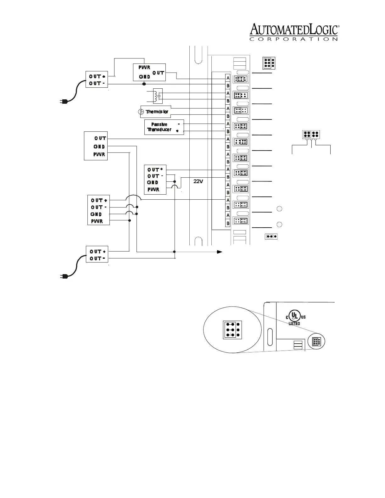
1. Be sure the S6104’s power is off before
wiring any inputs or outputs.
2. Connect the input wiring to the screw
terminals on the module as shown in
Figure 8.
NOTE
If a 4-20mA sensor uses an
external 24VAC power supply, connect
one leg of the 24VAC supply to the module
ground.
3. If using inputs 9 and 10 when wiring the
S6104 to a rooftop AHU, set the Input
Select jumper to the IN9/IN10 position.
See Figure 9. If using a LogiStat or
LogiStat Plus, see “LogiStat Wiring” on
page 10.
4. Set the Universal Input Mode Select
jumper for each input to indicate the type
of sensor used. Make sure the jumper is
positioned correctly, and be sure to grip
the jumper by the sides only. See Figure
10.
Figure 8. Input Wiring
15
16
17
18
20
19
14
13
12
11
10
9
8
7
6
5
4
3
2
1
IN-10
IN-9
IN-8
IN-7
IN-6
IN-5
IN-4
IN-3
IN-2
IN-1
B
A
B
A
B
A
B
A
B
A
B
A
B
A
B
A
B
A
B
A
IN10
LogiStat
Input Select
B - Gnd/Loop Power
A - Input Signal
38.4k
9600
CMnet Select
0-20 mA
0-5Vdc
dry-contact
Thermistor/
Mode Select
Universal Input
IN9/
Tx
Rx
Baud Select
5V Max, 20mA Max
Inputs
To Module Ground
Isolated DC
Power Supply
4Wire
4-20mA
Isolated DC
Power Supply
2Wire
4-20mA
2Wire
4-20mA
Dry Contact
2Wire
0-5VDC
4Wireusing
module power
Figure 9. Input Select set to IN9/IN10
LogiStat
IN9/IN10
IN10
LogiStat
Input Select
IN9/
E143900
TYPE: 006104
88FO
R
Management Equipment
Open Energy
 Loading...